"LbAP" and "LbAt" = 0. To restore the functioning after the alarm,
reprogram the automatic control functioning (rEG).
4.14 - AUXILIARY DIGITAL INPUTS
As alternative to the serial line, the instrument can be equipped
with
optoisolated auxiliary inputs (AUXIN1 and AUXIN2), by means of which
it's possible to select one of the 4 predetermined set point, to change the
instrument functioning state or both things. The auxiliary inputs have to be
activated by devices without potential as contacts or open collector (NPN
transistor), considering that the COM terminal is the negative common
one. The functioning of the auxiliary inputs is defined by the parameter
"rEar"
, which can assume the following values :
"FF" = No function
"Fr" = Set point selection
"rF" = Control state selection
"rr" = Set point selection (SP1or SP2) through AUXIN1 and instrument
state selection (control or Off) through AUXIN2.
The following table indicates the programmable functions related to the
inputs state (considering the connected contacts state as opened = off or
closed = on) and to the programmed auxiliary inputs functioning mode:
SP2
OFF
Control
SP4
on
on
SP2
Control
OFF
SP3
on
off
SP1
OFF
-
SP2
off
on
SP1
Control
Man. Contr.
SP1
off
off
SPn
Control
State
Control
State
SPn
AUXIN2
AUXIN1
"rr"
"rF
"
"Fr
"
Whenever the digital inputs are used to establish the control mode ("rEAr"
= "rF") do program on parameter
"rEdF"
the control power, in case of
manual control.
4.15 - RS 485 SERIAL INTERFACE
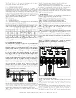
The instrument can be equipped with an RS 485 serial communication
interface, by means of which it's possible to connect the regulator with a
net on which are connected other instruments (regulators or PLC) all
depending typically on a personal computer used as plant supervisor.
Through personal computer it's possible to acquire all the functioning
information and to program all the instrument configuration parameters.
The software protocol adopted for THP94 is a derivative from MODBUS
RTU or JBUS protocol (AEG Schneider Automation, Inc. Trade Mark)
widely used in several PLC and supervision programs available on the
market (THP94 protocol manual is available on request). The interface
circuit is mounted with CMOS components that presents weak pull
up/down currents absorbed and therefore allows to connect till 100 THP94
instruments on the same line. To maintain the line on rest conditions it's
required the connection with a 100 Ohm resistance (Rt) at the end of the
line. The instrument is equipped with two terminals called A(L+) and B(L-)
that have to be connected with all the namesake terminals of the net. For
the wiring operation it's enough then to interlace a double cable
(telephonic type) and to connect on ground all the GND terminals.
Anyway, particularly when the net results very long or noised and being
present potential differences between the GND terminals, it's advisable to
adopt a screened cable wired as in the drawing.
Adopting this electrical drawing and having care that the total capacity of
the line would not be higher than 200 nF, the total length of the line can
reach a maximum of 1500 meters. If the instrument is equipped with the
serial interface, the parameters to be programmed are the following :
"nStA"
: Address of the station. Set a different number for each station,
from 1 to 255.
"bAud"
: Transmission speed (baud-rate), from 300 to 9600 baud.
All the stations have to be the same transmission speed.
"PAcS"
: Programming access. If programmed as "LoCL" this means that
the instrument is programmable just from the keyboard, if programmed as
"LorE" it's programmable both from the keyboards and serial line.
When is tried to accede to programming from the keyboard while is having
place a communication through the serial door, the instrument visualise
"buSy"
to indicate the busy state.
5 - PROGRAMMING
In any state of control, pushing "P" key and keeping it pushed for about 3
seconds, is possible to accede to selection menu "SEL".
By means of "UP" key it's possible then to run over the selections :
"rEG"
: permits to turn the regulator into automatic control state
"OPEr"
: permits to get into the operative parameters menu
"ConF"
: permits to get into the configuration parameters menu
"SPn"
: permits to select the active Set point and appears only if par.
"nSP" is higher than 1
"tunE"
: it permits to activate the Autotuning or Selftuning function and
appears only if the parameter "Auto" is different from "no" or if the
parameter "SELF" is "yES".
"OFF"
: permits to switch the instrument into "OFF" state
" OPLO"
: permits to switch the instrument into manual control state and
then to program the % control value to apply. Appears only if par.
"EnOL" is programmes as "yES". Once selected the desired parameter
push "P" key to confirm it.
The selections "OPEr", "ConF" and "SPn" give
access to minor menu containing other parameters or options and more
precisely :
"OPEr"
: Operative parameters menu
:
contains the Set point parameters
and the alarms parameters
"ConF"
: Configuration parameters menu
:
contains the functioning
configuration parameters ( Alarms and input configuration, etc.)
"SPn"
: Selection menu of the active Set point
:
contains the selections of
the possible Set point to define as active.
Inside of these menu, on the upper display appears the parameter name
selected, while on the lower display appears its actual value.
The keys have then the following functions :
"LEFT"
: used to shift the "cursor" (flashing) on the figure that is desired
to modify
"UP"
: used to increase the figure on which is placed the "cursor". In
case of parameters not numerical, "UP" key is needed to select the
available options
"P"
: used to confirm the programmed data and pass then to the next
parameter. Keeping pushed "P" key and pushing "UP" key, the parameters
run over backwards. To accede to "ConF" menu it's requested a
PASSWORD. Set, using "UP" and "LEFT" keys, the number written on the
TECNOLOGIC - THP 94
USER MANUAL (I - GB) - Vr. 05 - ISTR 01195 - PAG. 18


