


Page 125
TMP86PM29BUG
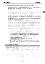
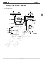
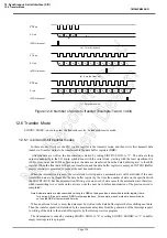
11.4 Transfer Rate
The baud rate of UART is set of UARTCR1<BRG>. The example of the baud rate are shown as follows.
When TC5 is used as the UART transfer rate (when UARTCR1<BRG> = “110”), the transfer clock and transfer
rate are determined as follows:
Transfer clock [Hz] = TC5 source clock [Hz] / TTREG5 setting value
Transfer Rate [baud] = Transfer clock [Hz] / 16
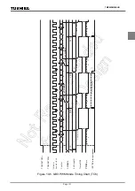
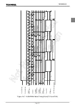
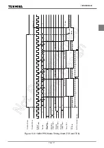
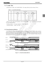
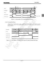
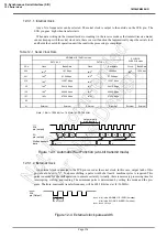
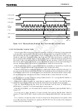
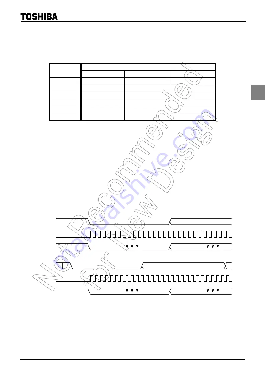
11.5 Data Sampling Method
The UART receiver keeps sampling input using the clock selected by UARTCR1<BRG> until a start bit is
detected in RXD pin input. RT clock starts detecting “L” level of the RXD pin. Once a start bit is detected, the start
bit, data bits, stop bit(s), and parity bit are sampled at three times of RT7, RT8, and RT9 during one receiver clock
interval (RT clock). (RT0 is the position where the bit supposedly starts.) Bit is determined according to majority
rule (The data are the same twice or more out of three samplings).
Figure 11-4 Data Sampling Method
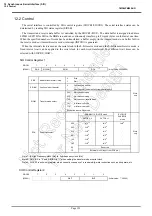
Table 11-1 Transfer Rate (Example)
BRG
Source Clock
16 MHz
8 MHz
4 MHz
000
76800 [baud]
38400 [baud]
19200 [baud]
001
38400
19200
9600
010
19200
9600
4800
011
9600
4800
2400
100
4800
2400
1200
101
2400
1200
600
RT0
1
2
3
4
5
6
7
8
9 10 11 12 13 14 15 0
1
2
3
4
5
6
7
8
9 10 11
Bit 0
Start bit
Bit 0
Start bit
(a) Without noise rejection circuit
RT clock
Internal receive data
RT0
1
2
3
4
5
6
7
8
9 10 11 12 13 14 15 0
1
2
3
4
5
6
7
8
9 10 11
Bit 0
Start bit
Bit 0
Start bit
RT clock
Internal receive data
(b) With noise rejection circuit
RXD pin
RXD pin
Summary of Contents for TLCS-870/C Series
Page 1: ...8 Bit Microcontroller TLCS 870 C Series TMP86PM29BUG ...
Page 6: ...TMP86PM29BUG ...
Page 7: ...Revision History Date Revision 2007 10 11 1 First Release 2008 8 29 2 Contents Revised ...
Page 9: ......
Page 15: ...vi ...
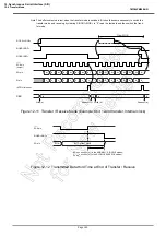
Page 19: ...Page 4 1 3 Block Diagram TMP86PM29BUG 1 3 Block Diagram Figure 1 2 Block Diagram ...
Page 23: ...Page 8 1 4 Pin Names and Functions TMP86PM29BUG ...
Page 48: ...Page 33 TMP86PM29BUG ...
Page 49: ...Page 34 2 Operational Description 2 3 Reset Circuit TMP86PM29BUG ...
Page 61: ...Page 46 3 Interrupt Control Circuit 3 8 External Interrupts TMP86PM29BUG ...
Page 81: ...Page 66 6 Watchdog Timer WDT 6 3 Address Trap TMP86PM29BUG ...
Page 135: ...Page 120 10 8 Bit TimerCounter TC5 TC6 10 1 Configuration TMP86PM29BUG ...
Page 145: ...Page 130 11 Asynchronous Serial interface UART 11 9 Status Flag TMP86PM29BUG ...
Page 165: ...Page 150 13 10 bit AD Converter ADC 13 6 Precautions about AD Converter TMP86PM29BUG ...
Page 183: ...Page 168 15 LCD Driver 15 4 Control Method of LCD Driver TMP86PM29BUG ...
Page 201: ...Page 186 18 Electrical Characteristics 18 9 Handling Precaution TMP86PM29BUG ...
Page 203: ...Page 188 19 Package Dimensions TMP86PM29BUG ...
Page 205: ......


