Theory of Operation
STD Bus Cascaded Interrupts
To allow for a greater number of interrupts, additional interrupt
controllers may be added to the STD bus system, allowing each
interrupt source to generate a unique vector for its service routine.
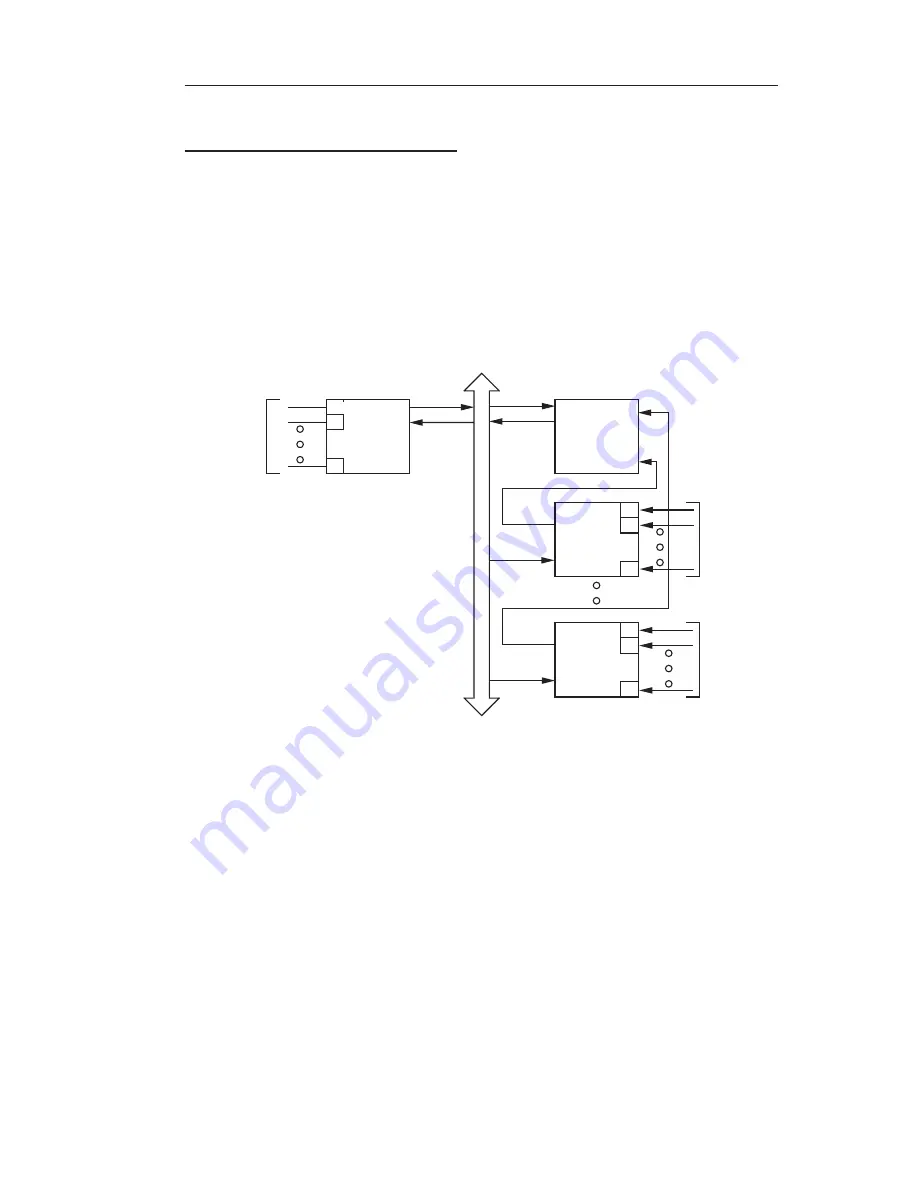
The ZT 8809A supports the STD-80 implementation of cascaded
interrupt controllers, useful for demanding applications with a large
number of interrupt sources. The system is illustrated in Figure 3-4.
0
1
7
INTERRUPT
SOURCE
1-8
ZT 8808A/
ZT 8809A
INTRQ*
INTAK*
INTRQ*
INTAK*
INTRQ*
INTAK*
INTERRUPT
SOURCE
9-16
0
1
7
0
1
7
INTERRUPT
SOURCE
41-48
UP TO
EIGHT
INTER-
RUPTS
UP TO
EIGHT
INTER-
RUPTS
UP TO
EIGHT
INTER-
RUPTS
INTRQ*
INTAK*
STD BUS
Figure 3–4. Large Scale Vectored Structure.
Backplane interrupt INTRQ* and any of the frontplane interrupts may
be used to cascade interrupt controllers. The interrupt output from the
"slave" interrupt controller in the system is tied to the interrupt request
input on the ZT 8809A "master" interrupt controller, and the PIC
programmed accordingly.
Then if an interrupt request from a
cascaded interrupt controller is to be serviced, the ZT 8809A drives a
3-bit address known as the cascade address onto A8 through A10 of
the STD bus during the interrupt acknowledge cycle. This 3-bit
address selects one of the cascaded interrupt controllers to provide an
interrupt vector for the requesting input.
This interrupt scheme
supports up to 48 interrupts, in addition to the two on board, each with
3-13


