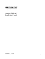
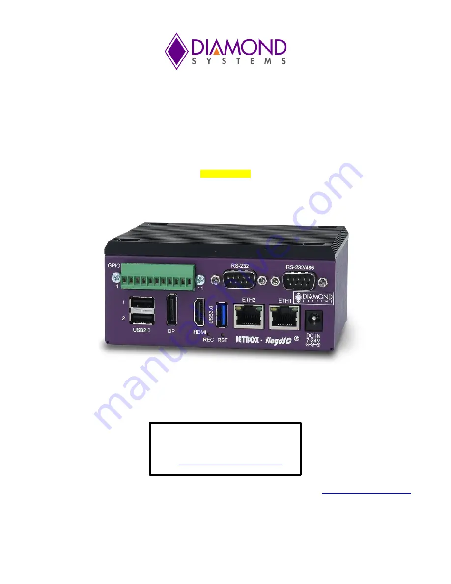
JETBOX FLOYD-SC
™
NVIDIA
®
Jetson Nano / TX2 NX / Xavier NX System
User Manual
PRELIMINARY
© Copyright 2022
Diamond Systems Corporation
FOR
TECHNICAL
SUPPORT
PLEASE
CONTACT:
Email:
The Diamond Systems JB-FLDSC-NAO-02 is a versatile and high-quality product designed to meet your needs. The user manual provides detailed instructions on how to maximize the product's performance and functionality. Download the manual for free from 88.208.23.73:8080 to ensure you get the most out of your purchase.
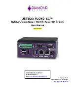
JETBOX FLOYD-SC
™
NVIDIA
®
Jetson Nano / TX2 NX / Xavier NX System
User Manual
PRELIMINARY
© Copyright 2022
Diamond Systems Corporation
FOR
TECHNICAL
SUPPORT
PLEASE
CONTACT:
Email: