INDUSTRIAL I/O PACK SERIES APCe8650
PCI BUS CARRIER BOARD
Acromag, Inc. Tel: 248-295-0310
- 20 -
www.acromag.com
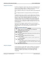
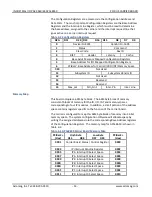
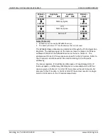
IP Module Memory Space - (Read/Write)
Each IP module may contain up to 8M bytes of Memory Space accessed as 16-
bit words. The four IP module Memory spaces are accessible at fixed offsets
from PCIBar2. IP modules may not fully decode their Memory space and may
use only byte or word accesses. See each IP module’s User Manual for
details.
GENERATING INTERRUPTS
Interrupt requests originate from the carrier board in the case of an access
time out and from the IP modules. Each IP may support 0, 1, or 2 interrupt
requests. Upon an IP module interrupt request the carrier passes the
interrupt request onto the host, provided that the carrier board is enabled for
interrupts within the Carrier Board Status Register.
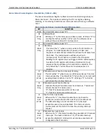
Sequence of Events for Processing an Interrupt
Perform any IP specific configuration required - do for each supported IP
interrupt request.
Set the interrupt enable bit in the Carrier Board Status Register by writing a
"1" to bit 2.
The IP module asserts an interrupt request to the carrier board (asserts
interrupt request line IntReq0* or IntReq1*).
If the INTx virtual wire interrupt signaling method is being used, the carrier
transmits an “Assert_INTx” message. When using MSI interrupts, a MSI
interrupt message is sent.
The interrupt service routine determines which IP module caused the
interrupt by reading the carrier interrupt pending register. If multiple
interrupts are pending the interrupt service routine software determines
which IP module to service first. If legacy PCI interrupts are used then the
interrupts could be shared and can be from any slot on the backplane or from
the mother board itself. The driver must first check that the interrupt came
from the PCIe carrier by reading the carrier interrupt pending register. When
using MSI interrupts, the interrupting carrier will be uniquely identified. A
polling sequence to identify the interrupting carrier is not needed.
The interrupt service routine accesses the interrupt space of the IP module
selected to be serviced. Note that the interrupt space accessed must
correspond to the interrupt request signal driven by the IP module.
The carrier board will assert the INTSEL* signal to the appropriate IP together
with (carrier board generated) address bit A1 to select which interrupt
request is being processed (A1 low corresponds to INTREQ0*; A1 high
corresponds to INTREQ1*).
The IP module receives an active INTSEL* signal from the carrier and supplies
its interrupt vector to the host system during this interrupt acknowledge
cycle. An IP module designed to release its interrupt request on acknowledge

