•
Pin Description
Number
Pin Description
Number
GND
1
GND
26
CLK
2
+5V
27
Reset*
3
R/W*
28
DOO
4
IDSEL*
29
DO1
5
DMAReq0-
30
D02
6
MEMSEL"
31
D03
7
DMAReql"
32
D04
8
IntSel"
33
D05
9
DMAck0'
34
D06
10
IOSEL*
35
D07
11
RESERVED
36
D08
12
Al
37
D09
13
DMAEnd"
38
D10
14
A2
39
D11
15
ERROR"
40
D12
16
A3
41
D13
17
INTReq0"
42
D14
18
A4
43
D15
19
INTReql"
44
BSO*
20
A5
45
B S I '
21
STROBE*
46
-12V
22
A6
47
+12V
23
ACK*
48
+5V
24
RESERVED
49
GND
25
GND
50
•
SERIES IP220 INDUSTRIAL I/O PACK
1
2
-BIT HIGH-DENSITY ANALOG OUTPUT MODULE
Analog Output Noise and Grounding Considerations
All
output channels are referenced to analog common on the
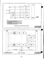
module (See Drawing 4501-440 for analog output connections), but
each channel has a separate return (minus lead) to maintain
accuracy and reduce noise. Still, the accuracy of the voltage output
depends on the amount of current loading (impedance of the load)
and the length (Impedance) of the cabling. High impedance loads
(e.g. loads > 1001(12) provide the best accuracy. For low impedance
loads, the IP220 can source up to 5mA, but the effects of source
and cabling resistance should be considered.
Output common is electrically connected to the IP module
ground. A s such, the IP220 is non-isolated between the logic and
field I/O grounds. Consequently, the field I/O connections are not
isolated from the carrier board and backplane. Care should be taken
in designing installations without isolation to avoid noise pickup and
ground loops caused by multiple ground connections. This is
particularly important for analog outputs when a high level of
accuracy/resolution is needed (e.g. 12-bits or more). R e f e r to
Drawing 4501-440 for example output and grounding connections.
Contact your Acromag representative for information on our many
isolated signal conditioning products that could be used to provide
isolated voltage or current outputs when used in conjunction with
the
IP220
output module.
IP Logic Interface Connector (P1)
P1 of the IP
module provides the logic interface to the mating
connector on the carrier board. This connector is a 50-pin female
receptacle header (AMP 173279-3 or equivalent) which mates to the
male connector of the carrier board (AMP 173280-3 or equivalent).
This provides excellent connection integrity and utilizes gold-plating
in the
mating area. Threaded metric M2 screws and spacers are
supplied with the IP module to provide additional stability for harsh
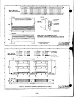
environments (see Drawing 4501-434 for assembly details). Field
and logic side connectors are keyed to avoid incorrect assembly.
The pin assignments of P1 are standard for all IP modules
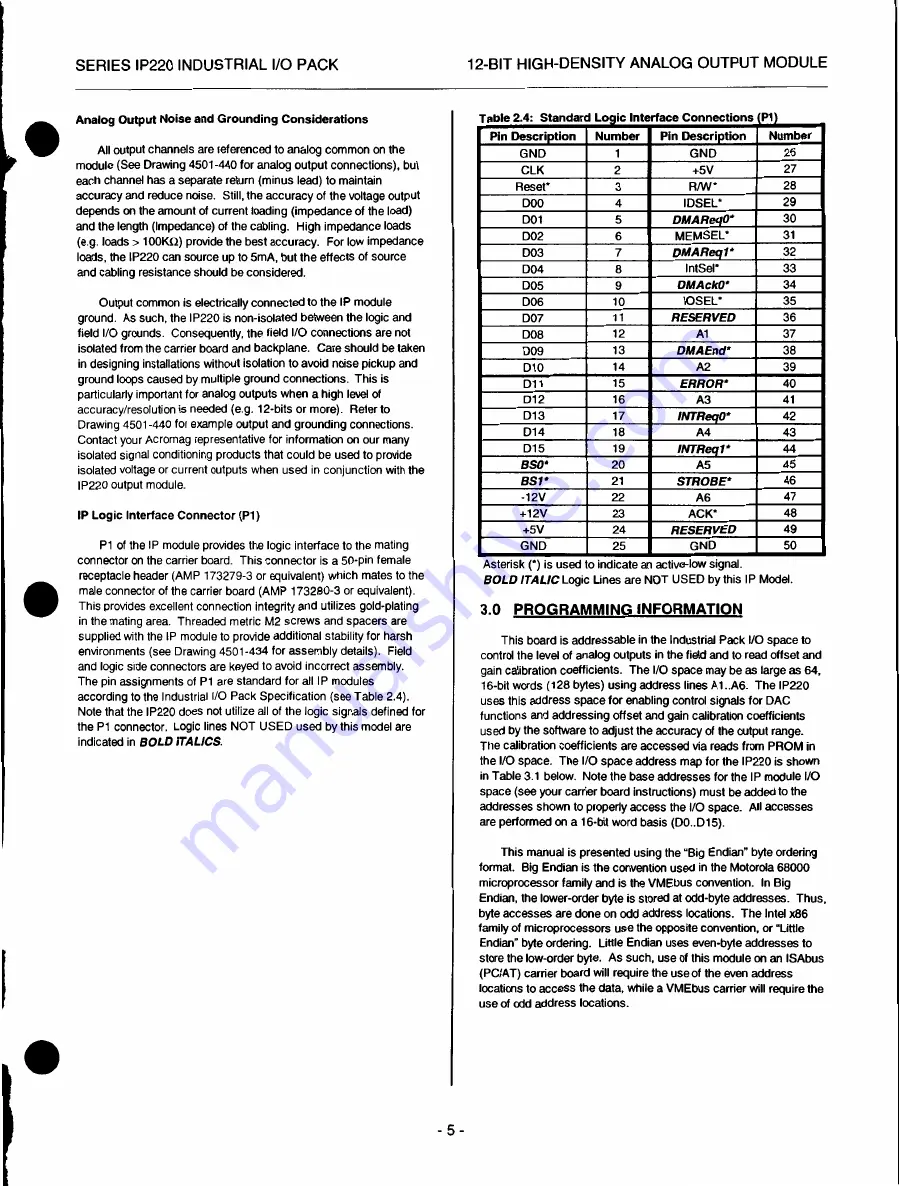
according to the Industrial I/O Pack Specification (see Table 2.4).
Note that the IP220 does not utilize all of the logic signals defined for
the P1 connector. Logic lines NOT USED used by this model are
indicated in BOLD ITALICS.
Table 2.4: Standard Logic Interface Connections (P1
Asterisk (*) is used o indicate an active-low signal.
BOLD ITALIC
Logic Lines are NOT USED by this IP Model.
3.0 PROGRAMMING INFORMATION
This board is addressable in the Industrial Pack I/O space to
control the level of analog outputs in the field and to read offset and
gain calibration coefficients. T h e I/O space may be as large as 64,
16-bit words (128 bytes) using address lines A1..A6. T h e IP220
uses this address space for enabling control signals for DAC
functions and addressing offset and gain calibration coefficients
used by the software to adjust the accuracy of the output range.
The calibration coefficients are accessed via reads from PROM in
the I/O space. T h e I/O space address map for the IP220 is shown
in Table 3.1 below. Note the base addresses for the IP module I/O
space (see your carrier board instructions) must be added to the
addresses shown to properly access the I/O space. All accesses
are performed on a 16-bit word basis (D0..D15).
This manual is presented using the "Big Endian" byte ordering
format. Big Endian is the convention used in the Motorola 68000
microprocessor family and is the VMEbus convention. I n Big
Endian, the lower-order byte is stored at odd-byte addresses. Thus,
byte accesses are done on odd address locations. T h e Intel x86
family of microprocessors use the opposite convention, or "Little
Endian" byte ordering. Little Endian uses even-byte addresses to
store the low-order byte. A s such, use of this module on an ISAbus
(PC/AT) carrier board will require the use of the even address
locations to access the data, while a VMEbus carrier will require the
use of odd address locations.
- 5 -


