SERIES IP220 INDUSTRIAL I/O PACK
1
2
-BIT HIGH-DENSITY ANALOG OUTPUT MODULE
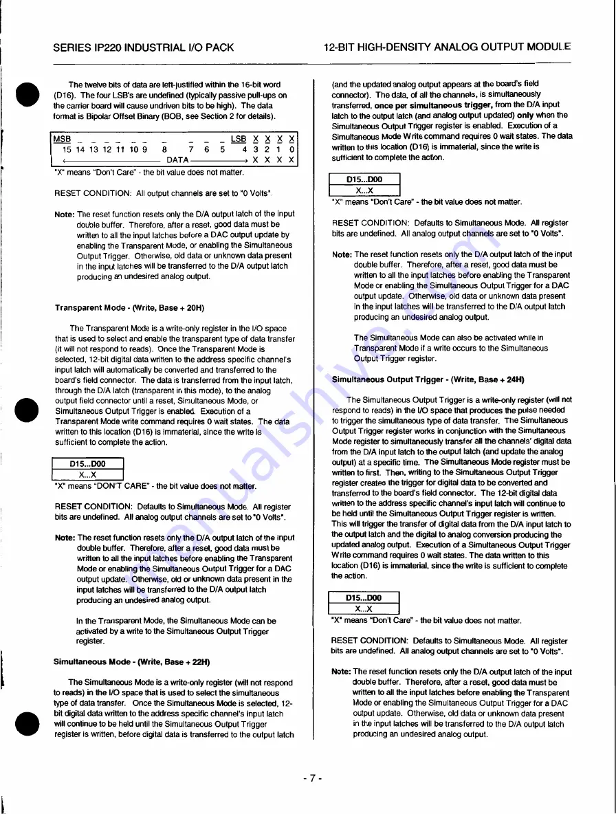
The twelve bits of data are left-justified within the 16-bit word
(D16). The four LSB's are undefined (typically passive pull-ups on
the carrier board will cause undriven bits to be high). The data
format is Bipolar Offset Binary (BOB, see Section 2 for details).
MSB
_
_ _ _
_
_ _ LSB X X X X
15 14 13 12 11 10 9 8
7
6 5 4 3 2 1 0
D
A
T
A
>
X
X
X
X
"X" means "Don't Care" - the bit value does not matter.
RESET CONDITION: All output channels are set to "0 Volts".
Note: The reset function resets only the D/A output latch of the input
double buffer. Therefore, after a reset, good data must be
written to all the input latches before a DAC output update by
enabling the Transparent Mode, or enabling the Simultaneous
Output Trigger. Otherwise, old data or unknown data present
in the input latches will be transferred to the D/A output latch
producing an undesired analog output.
Transparent Mode - (Write, Base + 20H)
The Transparent Mode is a write-only register in the I/O space
that is used to select and enable the transparent type of data transfer
(it will not respond to reads). Once the Transparent Mode is
selected, 12-bit digital data written to the address specific channel's
input latch will automatically be converted and transferred to the
board's field connector. The data is transferred from the input latch,
through the D/A latch (transparent in this mode), to the analog
output field connector until a reset, Simultaneous Mode, or
Simultaneous Output Trigger is enabled. Execution of a
Transparent Mode write command requires 0 wait states. The data
written to this location (D16) is immaterial, since the write is
sufficient to complete the action.
D15...D00
X...X
"X" means "DON'T CARE" - the bit value does not matter.
RESET CONDITION: Defaults to Simultaneous Mode. All register
bits are undefined. All analog output channels are set to "0 Volts".
Note:
The reset function resets only the D/A output latch of the input
double buffer. Therefore, after a reset, good data must be
written to all the input latches before enabling the Transparent
Mode or enabling the Simultaneous Output Trigger for a DAC
output update. Otherwise, old or unknown data present in the
input latches will be transferred to the D/A output latch
producing an undesired analog output.
In the Transparent Mode, the Simultaneous Mode can be
activated by a write to the Simultaneous Output Trigger
register.
Simultaneous Mode - (Write, Base + 22H)
The Simultaneous Mode is a write-only register (will not respond
to reads) in the I/O space that is used to select the simultaneous
type of data transfer. Once the Simultaneous Mode is selected, 12-
bit digital data written to the address specific channel's input latch
will continue to be held until the Simultaneous Output Trigger
register is written, before digital data is transferred to the output latch
(and the updated analog output appears at the board's field
connector). The data, of all the channels, is simultaneously
transferred, once per simultaneous trigger, from the D/A input
latch to the output latch (and analog output updated)
only
when the
Simultaneous Output Trigger register is enabled. Execution of a
Simultaneous Mode Write command requires 0 wait states. The data
written to this location (D16) is immaterial, since the write is
sufficient to complete the action.
D15...D00
X...X
"X" means "Don't Care" - the bit value does not matter.
RESET CONDITION: Defaults to Simultaneous Mode. All register
bits are undefined. All analog output channels are set to "0 Volts".
Note: The reset function resets only the D/A output latch of the input
double buffer. Therefore, after a reset, good data must be
written to all the input latches before enabling the Transparent
Mode or enabling the Simultaneous Output Trigger for a DAC
output update. Otherwise, old data or unknown data present
in the input latches will be transferred to the D/A output latch
producing an undesired analog output.
The Simultaneous Mode can also be activated while in
Transparent Mode if a write occurs to the Simultaneous
Output Trigger register.
Simultaneous Output Trigger - (Write, Base + 24H)
The Simultaneous Output Trigger is a write-only register (will not
respond to reads) in the I/O space that produces the pulse needed
to trigger the simultaneous type of data transfer. The Simultaneous
Output Trigger register works in conjunction with the Simultaneous
Mode register to simultaneously transfer all the channels' digital data
from the D/A input latch to the output latch (and update the analog
output) at a specific time. The Simultaneous Mode register must be
written to first. Then, writing to the Simultaneous Output Trigger
register creates the trigger for digital data to be converted and
transferred to the board's field connector. The 12-bit digital data
written to the address specific channel's input latch will continue to
be held until the Simultaneous Output Trigger register is written.
This will trigger the transfer of digital data from the D/A input latch to
the output latch and the digital to analog conversion producing the
updated analog output. Execution of a Simultaneous Output Trigger
Write command requires 0 wait states. The data written to this
location (D16) is immaterial, since the write is sufficient to complete
the action.
D15...D00
X...X
'X' means "Don't Care" - the bit value does not matter.
RESET CONDITION: Defaults to Simultaneous Mode. All register
bits are undefined. All analog output channels are set to "0 Volts".
Note:
The reset function resets only the D/A output latch of the input
double buffer. Therefore, after a reset, good data must be
written to all the input latches before enabling the Transparent
Mode or enabling the Simultaneous Output Trigger for a DAC
output update. Otherwise, old data or unknown data present
in the input latches will be transferred to the D/A output latch
producing an undesired analog output.
- 7 -


