SERIES
IP220 INDUSTRIAL I/O PACK
1
2
-BIT HIGH-DENSITY ANALOG OUTPUT MODULE
The Simultaneous Mode can also be activated while in
Transparent Mode if a write occurs to the Simultaneous
Output Trigger register.
Channel Offset/Gain
Error Coeff.
- (Read, Base + 41 to
7FH)
Calibration data is provided in the form of calibration
coefficients, so the user can adjust and improve the accuracy of the
analog output voltage over the uncalibrated state. Each channel's
unique offset and gain calibration coefficients are stored in a PROM.
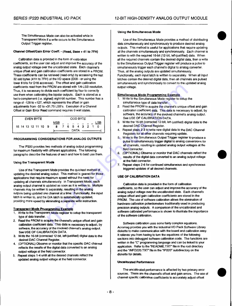
These coefficients can be retrieved (read-only) by accessing the last
32 odd bytes (41H to 7FH) of the I/O space (D08 - or using the
lower 8 bits for D16 accesses). The offset and gain calibration
coefficients read from the PROM are stored with 1/4-LSB resolution.
Thus, it is necessary to divide each coefficient by four to correctly
use them when calibrating the bipolar outputs. Each is stored as a
two's-complement (i.e. signed) eight-bit number. This number has a
range of -128 to +127, which represents the offset or gain
adjustments from -32 to +31.75 LSB's. Execution of a Channel
Offset or Gain Error Read command requires 0 wait states.
EVEN
BYTE
O
D
D
BYTE
MSB
LSB
15 14 13 12 11 1 0 9 8 7 6 5 4 3 2 1 0
DATA >
I
PROGRAMMING CONSIDERATIONS FOR ANALOG OUTPUTS
The IP220 provides two methods of analog output programming
for maximum flexibility with different applications. The following
paragraphs describe the features of each and how to best use them.
Using the Transparent Mode
Use of the Transparent Mode provides the quickest method of
updating the desired analog output. This method is geared for those
applications that require maximum speed without the need for
updating all channels simultaneously. In Transparent Mode, each
analog output channel is updated as soon as it is written to. Multiple
channels may be written to separately, resulting in the analog
outputs being updated one channel at a time. Functionally, the input
latch is written to, and the D/A latch is automatically updated,
providing more speed by eliminating a separate write instruction.
Transparent Mode Proarammina Example
1. Write to the Transparent Mode register to setup the transparent
type of data transfer.
2.
Read
the PROM to acquire the channel's unique offset and gain
calibration coefficient data. This data is necessary to adjust, by
software, the accuracy of the involved channel's analog output.
See
USE
OF CALIBRATION DATA.
3. Write the 16-bit (corrected 12-bit, lett-justified) digital data to the
desired DAC Channel Register.
4. (OPTIONAL) Observe or monitor that the specific DAC channel
reflects the results of the digital data converted to an analog
output voltage at the field connector.
5. Repeat steps 1-4 until all the desired channels reflect the
updated analog output voltage at the field connector.
- 8 -
Using the Simultaneous Mode
Use of the Simultaneous Mode provides a method of distributing
data simultaneously and synchronously to produce desired analog
outputs. This method is useful for applications that require updating
all the
channels simultaneously and
synchronously. Each channel is
written to with the required 16-bit (12-bit, left-justified) data. When
all the required channels contain the desired digital data, then a write
to the Simultaneous Output Trigger register will produce a pulse to
simultaneously trigger each channel's digital to analog converter.
Thus, all the analog outputs are updated simultaneously.
Functionally, each input latch is written to separately. When all input
latches contain the desired digital data, then all channels are pulsed
simultaneously and synchronously to convert to the updated analog
output voltage.
Simultaneous Mode Proarammina Example
1. Write to the Simultaneous Mode register to setup the
simultaneous type of data transfer.
2. Read the PROM to acquire the channel's unique offset and gain
calibration coefficient data. This data is necessary to adjust, by
software, the accuracy of the involved channel's analog output.
See USE OF CALIBRATION DATA.
3. Write the 16-bit (corrected 12-bit, left-justified) digital data to the
desired DAC Channel Register.
4. Repeat steps 2-3 to write new digital data to the DAC Channel
Registers for all other channels requiring update.
5. Write to the Simultaneous Output Trigger register to produce a
pulse to simultaneously trigger digital to analog conversions for
all channels, resulting in updated analog output voltages at the
field connector.
6. (OPTIONAL) Observe or monitor that DAC
channels
reflect the
results of the digital data converted to an analog output voltage
at the field connector.
7. Repeat steps 2-6 for continued simultaneous and synchronous
triggered updates of all desired channels.
USE OF CALIBRATION DATA
Calibration data is provided in the form of calibration
coefficients, so the user can adjust and improve the accuracy of the
analog output voltage over the uncalibrated state. Each channel's
unique offset and gain calibration coefficients are stored in the
PROM. The use of software calibration allows the elimination of
hardware calibration potentiometers traditionally used in producing
precision analog outputs. A comparison of the uncalibrated and
software calibrated performance is shown to illustrate the importance
of the software calibration.
Software calibration uses some fairly complex equations.
Acromag provides you with the Industrial I/O Pack Software Library
diskette to make communication with the board and calibration easy.
It relieves you from having to turn the equations of the following
sections into debugged software calibration code. The functions are
written in the "C" programming language and can be linked to your
application. Refer to the "README.TXT" file in the root directory
and the "INFO220.TXT" file in the "IP220" subdirectory on the
diskette for details.
Uncalibrated Performance
The uncalibrated performance is affected by two primary error
sources. These are the channel's offset and gain errors. The use of
channel specific calibration coefficients to accurately adjust offset
•


