49
Chapter 4
Interrupt Control:
Enable the interrupt by setting bit0 as ‘1’.
When interrupt is activated it is necessary to read this specified bit0 to
reset the interrupt.
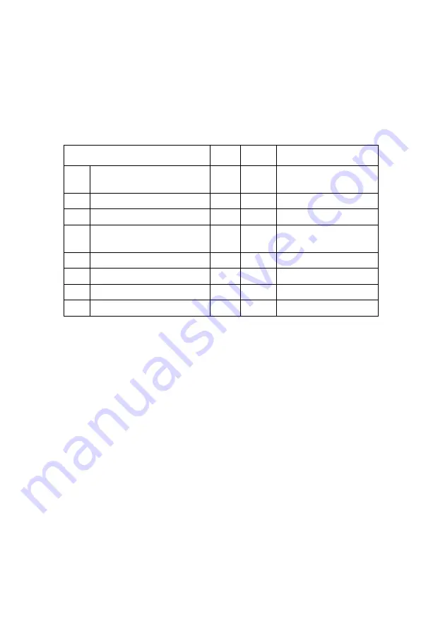
Kinds of registers and data bits
Description
Bits
R/W
Setting Range
R0
Preset counter data
24
R/W
0 to 16,777,215
(FFFFFF)
R1
FL register
13
W(R)
1 to 8,191 (1FFF)
R2
FH register
13
W(R)
1 to 8, 191 (1FFF)
R3
Acceleration/deceleration
rate register
10
W(R)
2 to 1, 023 (3FF)
R4
Multiplier register
10
W(R)
2 to 1, 023 (3FF)
R5
Set ramping-down point
16
W(R)
0 to 65, 535 (FFFF)
R6
Set idling pulse
3
W(R)
0 to 7
R7
Output type register
1
W(R)
0 to (1)
Note1
: * R/W: Read/Write register
W(R): Write only register. However, it can be
read using the extension monitor setting.
Note2
R7 is allowed to be 0 or 1.
R7 = 0, CW/CCW output type
R7= 1, Pulse/Direction output type
Summary of Contents for PCI-1243U
Page 1: ...PCI 1243U 4 Axis Stepping Motor Control Card User Manual ...
Page 8: ...PCI 1243U User Manual viii ...
Page 14: ...PCI 1243U User Manual 6 ...
Page 35: ...27 Chapter3 Figure 3 8 Point to Point Movement ...
Page 38: ...PCI 1243U User Manual 30 ...
Page 80: ...PCI 1243U User Manual 72 Appendix A Diagrams A 1 Jumper and Switch Layout ...
Page 82: ...PCI 1243U User Manual 74 ...
Page 88: ...PCI 1243U User Manual 80 ...


