Programmer’s Model
3-12
Copyright © 2002, 2003 ARM Limited. All rights reserved.
ARM DDI 0275D
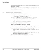
The AHB interface is enabled when the SoftwareCntl bit of the control register and the
SWEN
signal are ANDed.
The ETB11 registers and RAM accesses are controlled by separate read/write ports and
each has their own separate
HSEL
input. This enables the ETB11 RAM to share the
address space with main memory.
3.3.1
Restrictions on use of the AHB interface
The AHB interface can be used for two purposes:
•
to read trace data captured by the ETB11 from software
•
as system memory when tracing is not required.
When using the AHB interface to read trace data, the following are not permitted:
•
byte or halfword accesses when the memory does not support them
•
unaligned accesses
•
transfers larger than a word, for example 64-bit transfers.
Only aligned, single-word accesses are permitted.
Register access supports aligned, single-word accesses only.
Use of the AHB interface as system memory requires careful system design to ensure
that the memory is not required for system use when tracing is required. If you want to
use the AHB interface for this purpose, you must ensure the following:
•
the memory supports byte writes (see the
Embedded Trace Buffer Implementation
Guide
)
•
if connected to a 64-bit AHB bus, 64 bit operations are supported, see
the ETB11 in a 64-bit AHB system
This is to ensure that all ARM load/store instructions are supported.
Summary of Contents for ETB11
Page 6: ...List of Tables vi Copyright 2002 2003 ARM Limited All rights reserved ARM DDI 0275D ...
Page 8: ...List of Figures viii Copyright 2002 2003 ARM Limited All rights reserved ARM DDI 0275D ...
Page 46: ...Functional Description 2 26 Copyright 2002 2003 ARM Limited All rights reserved ARM DDI 0275D ...
Page 70: ...Signal Descriptions A 6 Copyright 2002 2003 ARM Limited All rights reserved ARM DDI 0275D ...
Page 78: ...Glossary Glossary 4 Copyright 2002 2003 ARM Limited All rights reserved ARM DDI 0275D ...

