195
4317I–AVR–01/08
AT90PWM2/3/2B/3B
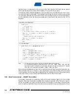
Note:
1. The example code assumes that the part specific header file is included.
For I/O Registers located in extended I/O map, “IN”, “OUT”, “SBIS”, “SBIC”, “CBI”, and “SBI”
instructions must be replaced with instructions that allow access to extended I/O. Typically
“LDS” and “STS” combined with “SBRS”, “SBRC”, “SBR”, and “CBR”.
The receive function example reads all the I/O Registers into the Register File before any com-
putation is done. This gives an optimal receive buffer utilization since the buffer location read will
be free to accept new data as early as possible.
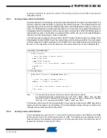
Assembly Code Example
(1)
USART_Receive:
;
Wait for data to be received
sbis
UCSRA, RXC0
rjmp
USART_Receive
;
Get status and 9th bit, then data from buffer
lds
r18, UCSRA
lds
r17, UCSRB
lds
r16, UDR
;
If error, return -1
andi
r18,(1<<FE0)|(1<<DOR0)|(1<<UPE0)
breq
USART_ReceiveNoError
ldi
r17, HIGH(-1)
ldi
r16, LOW(-1)
USART_ReceiveNoError:
;
Filter the 9th bit, then return
lsr
r17
andi
r17, 0x01
ret
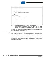
C Code Example
(1)
unsigned int
USART_Receive(
void
)
{
unsigned char
status, resh, resl;
/*
Wait for data to be received
*/
while
( !(UCSRA & (1<<RXC0)) )
;
/*
Get status and 9th bit, then data
*/
/*
from buffer
*/
status = UCSRA;
resh = UCSRB;
resl = UDR;
/*
If error, return -1
*/
if
( status & (1<<FE0)|(1<<DOR0)|(1<<UPE0) )
return
-1;
/*
Filter the 9th bit, then return
*/
resh = (resh >> 1) & 0x01;
return
((resh << 8) | resl);
}


