41
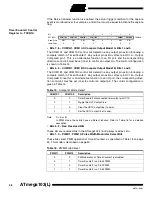
ATmega103(L)
0945G–09/01
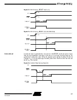
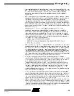
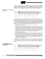
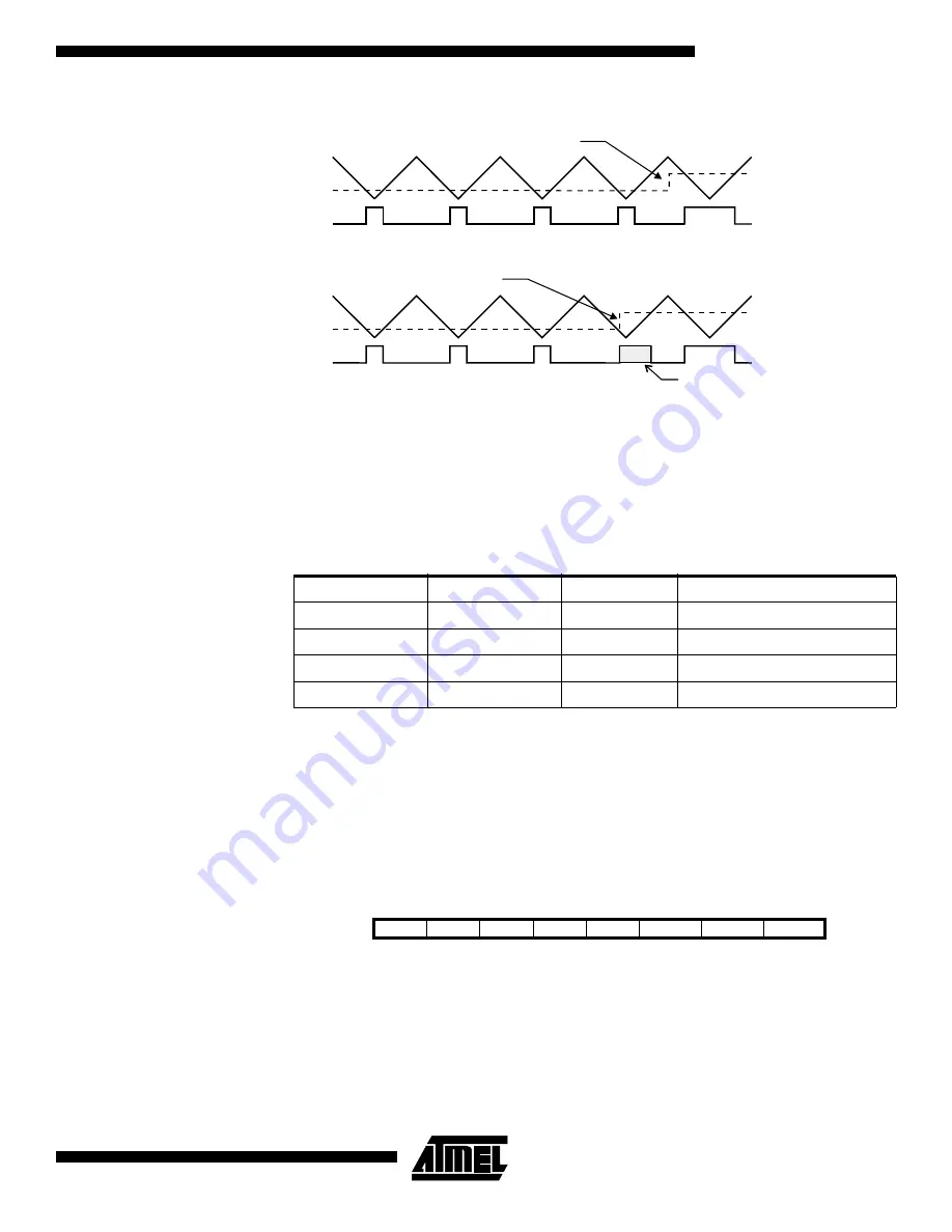
Figure 32.
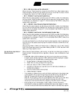
Effects on Unsynchronized OCR Latching
During the time between the write and the latch operation, a read from OCR0 or OCR2
will read the contents of the temporary location. This means that the most recently writ-
ten value always will read out of OCR0/2.
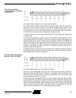
When the OCR register (not the temporary register) is updated to $00 or $FF, the PWM
output changes to low or high immediately according to the settings of COM21/COM20
or COM11/COM10. This is shown in Table 14.
Note:
n = 0 or 2
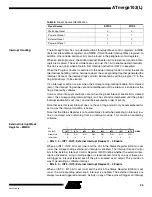
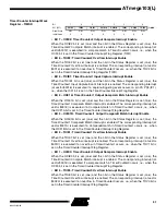
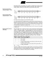
In PWM mode, the Timer Overflow flag, TOV0 or TOV2, is set when the counter
advances from $00. Timer Overflow Interrupts 0 and 2 operate exactly as in normal
Timer/Counter mode, i.e., it is executed when TOV0 or TOV2 is set, provided that Timer
Overflow interrupt and global interrupts are enabled. This also applies to the Timer Out-
put Compare flags and interrupts.
The frequency of the PWM will be Timer Clock Frequency divided by 510.
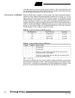
Asynchronous Status
Register – ASSR
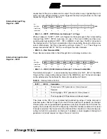
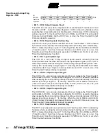
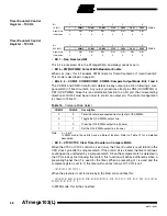
• Bits 7..4 – Res: Reserved Bits
These bits are reserved bits in the ATmega103(L) and always read as zero.
Table 14.
PWM Outputs OCRn = $00 or $FF
COMn1
COMn0
OCRn
Output PWMn
1
0
$00
L
1
0
$FF
H
1
1
$00
H
1
1
$FF
L
Counter Value
Compare Value
PWM Output
Synchronized OCR Latch
Counter Value
Compare Value
PWM Output
Unsynchronized OCR Latch
Glitch
Compare Value changes
Compare Value changes
Bit
7
6
5
4
3
2
1
0
$30 ($50)
–
–
–
–
AS0
TCN0UB
OCR0UB
TCR0UB
ASSR
Read/Write
R
R
R
R
R/W
R
R
R
Initial Value
0
0
0
0
0
0
0
0

