EM78P911A
8-bit Micro-controller
__________________________________________________________________________________________________________________________________________________________________
* This specification is subject to change without notice.
~ ~
17
12/19/2005 (V2.1)
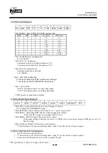
10. IOCF (Interrupt Mask Register)
7
6
5
4 3 2 1 0
INT3 FSK/CW
C8_2
C8_1
INT2 INT1 INT0
TCIF
* Bit 0 ~ 7 interrupt enable bit.
0: disable interrupt
1: enable interrupt
* IOCF Register is readable and writable.
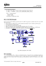
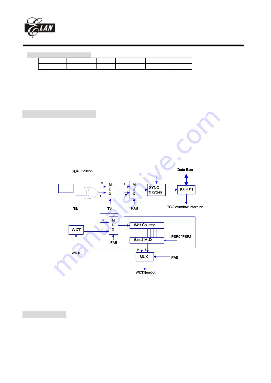
VII.3 TCC/WDT Prescaler
There is an 8-bit counter available as prescaler for the TCC or WDT. The prescaler is available for the TCC only or WDT
only at the same time.
•
An 8 bit counter is available for TCC or WDT determined by the status of the bit 3 (PAB) of the CONT register.
•
See the prescaler ratio in CONT register.
•
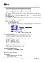
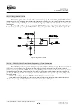
Fig. 10 depicts the circuit diagram of TCC/WDT.
•
Both TCC and prescaler will be cleared by instructions which write to TCC each time.
•
The prescaler will be cleared by the WDTC and SLEP instructions, when assigned to WDT mode.
•
The prescaler will not be cleared by SLEP instructions, when assigned to TCC mode.
Fig.10
Block
diagram
of
TCC
WDT
VII.4 I/O Ports
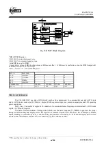
The I/O registers, Port 6 ~ Port 9, are bi-directional tri-state I/O ports. Port 7 can be pulled-high internally by
software control. The I/O ports can be defined as "input" or "output" pins by the I/O control registers (IOC6 ~ IOC9 ) under
program control. The I/O registers and I/O control registers are both readable and writable. The I/O interface circuit is shown
in Fig.11.
16.38KHz


