7-10
750/760 Feeder Management Relay
GE Multilin
7.3 MODBUS OPERATIONS
7 COMMUNICATIONS
7
7.3.5 READING TRACE MEMORY
All Trace Memory waveform data can be read from Modbus registers found in the address range 2100h to 215Fh. In order
to understand the following description, familiarity with the settings for Trace Memory is required; refer to Section 5.2.5:
Trace Memory on page 5–11.
The ‘Number of Trace Memory Triggers Since Last Clear’ register is incremented by one every time a new Trace Memory is
triggered. This register is cleared to zero when Trace Memory is cleared. When a new trigger occurs, the associated wave-
form data is assigned a ‘Trace Memory Number’ which is equal to the incremented value of this register; the newest data
will have a number equal to the Number of Trace Memory Triggers. This register can be used to determine if any new data
has been captured by periodically reading it to see if the value has changed; if the Number of Trace Memory Triggers has
increased then there is new data available.
The Trace Memory Buffer Organization setpoint determines the number of samples that are captured per channel for each
separate trigger. This setpoint also determines how many data triggers are stored in memory. For example if the setting is
4x1024 then there are 1024 samples per channel per trigger and the last three data triggers can be read from memory.
Note that only 64 samples of one data channel for a single waveform can be read from the Modbus memory map in a single
data packet. The ‘Trace Memory Selectors’ registers determine which waveform data can be read from the memory map.
The ‘Trace Memory Number Selector’ determines which Trace Memory can be read. For example, to read the data for
Trace Memory number 3, the value 3 must first be written to this register. Data for Trace Memory number 3 can now be
read from the ‘Trace Memory Information’ registers at addresses 2111h to 2119h. These registers include a trigger cause
(see the previous section for a description of the data format), a trigger time and date stamp, and the sampling frequency.
There is also the ‘Start Index’ and ‘Trigger Index’ which determine how to ‘unravel’ the data samples; see the description of
the circular data structure below.
The ‘Trace Memory Channel Selector’ determines which data channel samples can be read from the ‘Trace Memory Sam-
ples’ registers at addresses 2120h to 215Fh; refer to format F26 for a complete listing of the available data channels. For
example, to read Vc voltage samples a value of 6 is written to this register. Note that this register also determines the data
format of the samples.
The ‘Trace Memory Sample Selector’ (TMSS) determines which block of 64 samples can be read from the ‘Trace Memory
Samples’ registers. The number of samples stored for one channel is variable and depends on the ‘Buffer Organization’
setpoint. The ‘Number of Trace Memory Samples Stored’ register indicates the number of samples that have already been
accumulated for the selected Trace Memory Number; this register may have a value less than the total number of samples
that can be stored if a trigger just occurred and there are an appreciable number of post-trigger samples to capture.
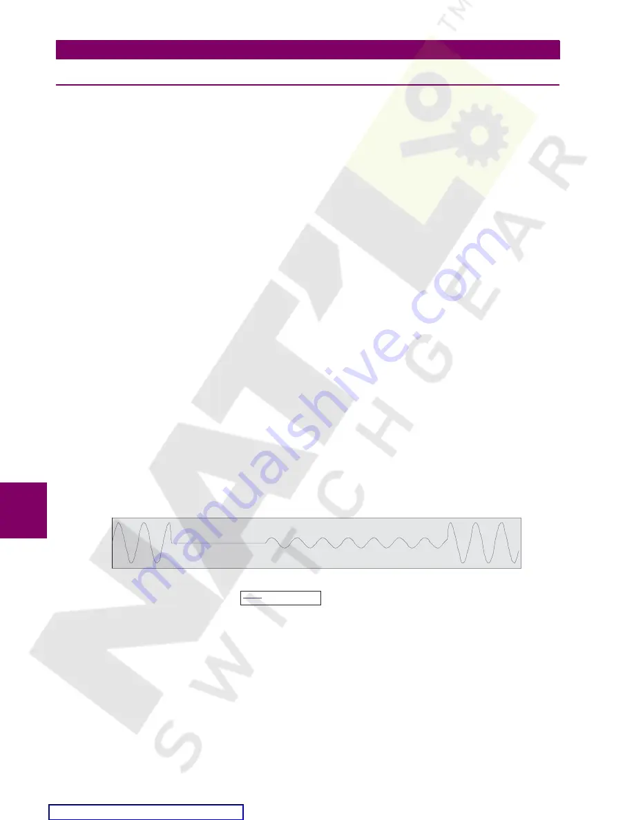
The samples are stored in a circular buffer; the figure below shows how a waveform might be stored for one channel. The
‘Trace Memory Start Index’ determines where the waveform begins in the buffer. Likewise, the ‘Trace memory Trigger
Index’ determines where the trigger point is. In this example the Start Index is 96 and the Trigger Index is 224; note that the
indices are always a multiple of sixteen.
Figure 7–1: TRACE MEMORY CIRCULAR BUFFER
The following example illustrates how information can be retrieved from Trace Memory:
1.
A SCADA system polls the Number of Trace Memory Triggers register once every minute. It now reads a value of 4
from the register where previously the value was 3 which means that a new data has been captured. The SCADA sys-
tem proceeds with the following steps to read all the waveform data. After these steps it resumes polling the Number of
Trace Memory Triggers register.
2.
Read the
TRACE MEMORY BUFFER ORGANIZATION
setpoint
3.
Write a value of 4 to the Trace Memory Number Selector.
4.
Read all the Trace Memory Information registers and store to SCADA memory.
-5000
-2500
0
2500
5000
0
16
32
48
64
80
96
112
128
144
160
176
192
208
224
240
256
Phase A Current


