33
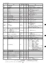
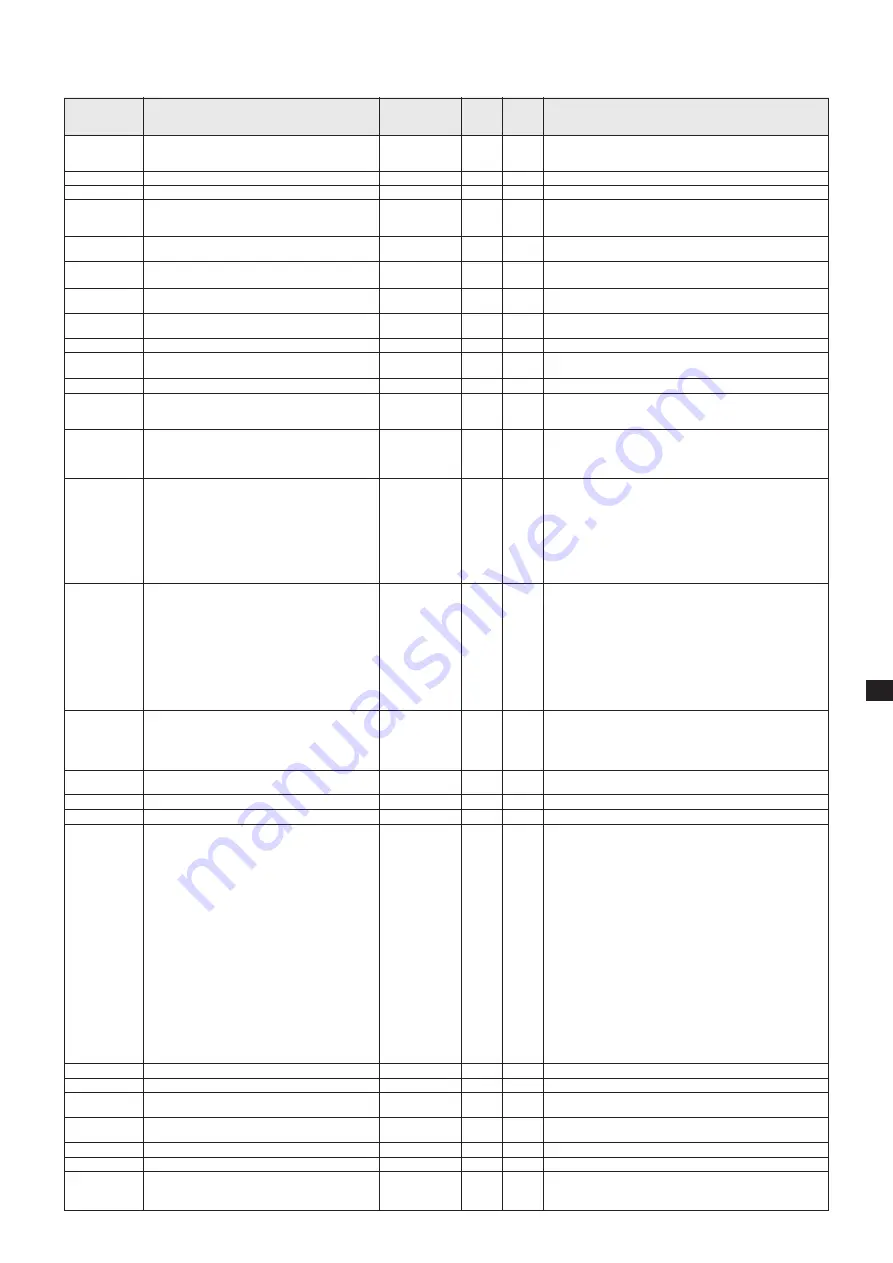
Table 2 : List of commands
Command
CNT0
CNT1
CNTQ
VER
L1
L0
S1
S0
AT***.*
ATQ
ATS
ATT
INT*
INTQ
INTSET***
or
INTSET*.**
CURE
α β γ
:
nnn,mmm.m,...
or
CURE
α β γ
:
nn.n,mmm.m,...
CUREQ
α
START*
STPQ
STOP
INP
LIF
LAMPCLR
PROG_1STEP
PROG_7STEP
PROG_N1STEP
PROG_N7STEP
PROG?
Description
Control mode setting
0: Front panel control
1: Command control
Inquiry of control mode
Version information
Lamp ON
Lamp OFF
Shutter OPEN
Shutter CLOSE
Shutter auto time setting
***.*(000.0 – 999.9 s)
Shutter auto time check
Shutter auto operation started
Shutter auto operation remaining time check
Diaphragm control : * is 0 to 4 numbers, meaning
0: Stop, 1: UP, 2: DOWN
3: UP (1point), 4: DOWN (1point)
Output intensity check
Output intensity setting
***: Output intensity (%)
*.**: Output intensity (W)
The memory cure program of the program No.
α
is set by the unit of % if
γ
=1 when using the
shutter mode
β
and by the unit of W if
γ
=2 when
using the shutter mode
β
.
α
: Program number (1 – 9)
β
: Shutter mode (1 or 2)
γ
: Unit of output intensity being set (1: %, 2: W)
nnn: Output intensity (%)
n.nn: Output intensity (W)
mmm.m: Time(s)
Comma division is used to link 7 steps.
Program number
α
memory cure program check
Program ** memory cure (setting in %) started
Memory cure progress state
Memory cure forced to end
Input pin data transmission
Lamp operation time check
Accumulated lamp operation time clear
Program mode set to 1STEP
(Automatic recognition of Optical Feedback Unit)
Program mode set to 7STEP
(Automatic recognition of Optical Feedback Unit)
% display program mode setting forced to 1STEP
% display program mode setting forced to 7STEP
Inquiry of program mode
Character string
returned from
light source side
CNT0OK
CNT1OK
CNT*
VER**-**-**
L1OK
L1NGxx
L0OK
L0NGxx
S1OK
S1NGxx
S0OK
--
ATOK
ATNG03
AT***.*
ATSOK
ATSNGxx
ATT***.*
INT*OK
INT*NG
INT***
INT*.**
INTSETOK
INTSETNGxx
CURE
α β γ
OK
CURE
α β γ
NG
CURE
α β γ
:
nnn,mmm.m,...
or
CURE
α β γ
:
n.nn,mmm.m,...
START*OK
START*NGxx
STP*
STOPOK
INP***
LIFOK****.*
LAMPCLROK
PROG_1STEPOK
PROG_7STEPOK
PROG_N1STEPOK
PROG_N7STEPOK
*STEP
Handled Handled
by
by
1STEP 7STEP
Yes
Yes
Yes
Yes
Yes
Yes
Yes
Yes
Yes
Yes
Yes
Yes
Yes
Yes
Yes
No
Yes
No
Yes
No
Yes
No
Yes
Yes
Yes
Yes
Yes
No
No
Yes
No
Yes
No
Yes
No
No
Yes
Yes
Yes
Yes
Yes
Yes
Yes
Yes
Yes
Yes
Yes
Yes
Yes
Yes
Yes
Yes
Yes
Remarks
When using the front panel control, ERR is output for all
commands other than this command.
The front panel control is used after the power is turned on.
* Control mode (0: from front, 1: from communication port)
NG trigger being applied (01)
Shutter is also closed at the same time if it is open.
If auto cure operation is at work, it is terminated (closed).
NG trigger being applied (01)
NG memory cure operation at work (02)
If memory cure operation is at work, it is terminated (closed).
If auto cure operation is at work, it is terminated (closed).
NG auto function being executed (03)
NG auto function being executed (03)
ATTOK00000.0 other than when being executed
NG memory cure operation at work (02)
***: Output intensity (%), *.**: Output intensity (W)
Output intensity (W) is used when the optical feedback unit
is connected and output intensity (%) is used when the opti-
cal feedback unit is unconnected.
NG shutter in auto-operation mode (03)
When the optical feedback unit is used and both conditions
of (1) shutter closed, and (2) lamp ON are met, set the out-
put intensity and adjust the diaphragm so that the set output
intensity value is obtained. If above conditions are not met,
doesn’t set the output intensity. When the optical feedback
unit is not used, set the output intensity regardless of the
shutter and lamp conditions and adjust the diaphragm so
that the set output intensity value is obtained.
NG memory cure operation at work (02)
α
: Program number (1 – 9),
β
: Shutter mode (1 or 2)
γ
: Unit of output intensity being set (1: %, 2: W)
nnn: Output intensity (%), n.nn: Output intensity (W), mmm.
m: Time(s)
Comma division is used to link 7 steps.
NG memory cure operation at work (02)
* Current step (1 – 7, 0 when unexecuted)
Shutter is closed and diaphragm is also stopped.
*** represent hexadecimal characters. When they are con-
verted to binary characters, each bit corresponds with the
status described below.
Bit0: 1: Lamp ON, 0: Lamp OFF
Bit1: 1: Lamp stable, 0: Lamp unstable
Bit2: 1: Shutter open, 0: Shutter closed
Bit3: 1: Diaphragm opening Min, 0: Otherwise
Bit4: 1: Diaphragm opening Max, 0: Otherwise
Bit5: 1: Initialize completed 0: Initialize going on
Bit6: 1: Lamp error 0: No error
Bit7: 1: Shutter error 0: No error
Bit8: 1: 4,000h (L8253:3,000h) accumulated time exceeded
0: Not exceeded
Bit9: 1: Overheat alarm 0: No alarm
Bit10: 1: Lamp forced OFF because of overheating
0: Lamp not forced OFF or lamp ON again after the
overheat alarm is cancelled.
Bit11: 1: Set output intensity not obtained when optical
feedback control is executed.
0: Set output intensity being obtained or optical
feedback control not executed.
Transmitted as soon as the INP command is received or the signal changes.
**** *: Lamp operation time (hour), minimum resolution 1 h
* represents the current program mode
1STEP: 1 % forced display 1STEP: N1
7STEP: 7 % forced display 7STEP: N7
Explanation of NG
........... XX represent the NG content.
01: Lamp trigger being applied, 02: Memory cure being executed, 03: Shutter auto function being executed,
04: Optical feedback unit unconnected, 05: Error not reaching memory cure setting of output intensity (W)
* and X represent 1 character of ASCII
Example: when xx=01, the data being communicated is H’30H’31.
Summary of Contents for LIGHTINGCURE LC8
Page 2: ...2...
Page 6: ...6 1 1 1 2 JIS C 7550 3 JIS T 8141 30 kV 15 1 MPa 10 4 MPa 40...
Page 8: ...8 25 80 10 cm 10 cm L9566 L9588 10 cm 10 cm 10 cm 10 cm...
Page 11: ...11 q OFF w e 1 MPa 10 r t y u...
Page 35: ...35 1 1 1 2 IEC 2006 IEC 62471 EMI 30kV 15 1MPa 10 4MPa 40...
Page 37: ...37 L9566 L9588 10cm 10cm 10cm 10cm 25 80 10cm 10cm...
Page 40: ...40 q OFF w e r t y 1MPa 10 u...
Page 54: ...54...
Page 55: ...55...


