Communication Interfaces
90
Value Parameter
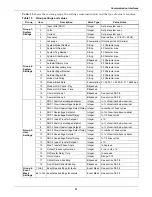
Item settings, depending on what they are, use various value types.
Table 14
provides a list of the
possible value types and their description.
Table 14
Value types
Type
Definition
Numeric
An integer numeric value in the units indicated by the item name. For example, a System Voltage
Rating of
480
would indicate
480 volts
.
Scaled
Similar to the Numeric, this value type is an integer that has been scaled, usually to remove decimal
points that would normally appear within the value. In this case, a value of
2.5
may actually be input
as simply
25
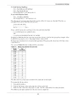
. For all Scaled types, the scaling appears in
Table 15
.
String
Certain settings are represented by alphanumeric character strings, such as setting the System
Model Number to ProductName.
Enumeratio
n
This type uses an indexed list to represent possible choices. One example is the Modem Baud Rate
which uses a value of
0
to select 2400 bps,
1
for 9600 bps and
2
for 19200 bps.
Bit-packed
This type of value uses a
hexadecimal binary word
, where each of the sixteen
bits
in the word has
the value of 1 (
True
) or 0 (
False
). Although somewhat difficult to use, it packs a large amount of data
within a single entry. A detailed description of this type appears in section
12.1.3 - Setting
Bitpacked Options With the Terminal
.
Event
Masks
This type is a specially formatted and is used to customize the behavior of each fault and alarm in
the system. See
12.1.4 - Setting Event Masks with the Terminal
for instructions on configuring
Event Mask parameters.
Summary of Contents for PDUTM
Page 25: ...Installation Drawings 17 7 0 INSTALLATION DRAWINGS Figure 7 Outline drawing 250A STS2 PDU ...
Page 42: ...Installation Drawings 34 Figure 24 Electrical field connections 250A STS2 PDU input with CB3 ...
Page 46: ...Installation Drawings 38 Figure 28 Electrical field connections 800A STS2 PDU input with CB3 ...
Page 63: ...Installation Drawings 55 Figure 45 Control wiring 800A STS2 PDU left side distribution ...
Page 64: ...Installation Drawings 56 Figure 46 Control wiring 800A STS2 PDU right side distribution ...
Page 65: ...Installation Drawings 57 Figure 47 Control connection location 250A STS2 PDU ...
Page 66: ...Installation Drawings 58 Figure 48 Control connection location 400 800A STS2 PDU ...
Page 68: ...Installation Drawings 60 Figure 50 Control wiring for the programmable relay board option ...
Page 69: ...Installation Drawings 61 Figure 51 Control wiring for the input contact isolator board option ...
Page 70: ...Installation Drawings 62 Figure 52 Control wiring for comms board ...
Page 71: ...Installation Drawings 63 Figure 53 Control wiring for the internal modem option ...
Page 72: ...Installation Drawings 64 Figure 54 Control wiring for the Network Interface Card NIC option ...
Page 73: ...Installation Drawings 65 Figure 55 Control wiring for the RS 232 Port ...
Page 74: ...Installation Drawings 66 Figure 56 Control wiring for remote source selection option ...
Page 75: ...Installation Drawings 67 Figure 57 Color LCD touch screen display ...
Page 155: ......

