4. Modbus RTU
4 - 10
4.8.4 Preset Multiple Registers (Writing data in multiple holding registers: 10h)
Data is written to consecutive holding registers for the specified number of data points starting from the
specified register address.
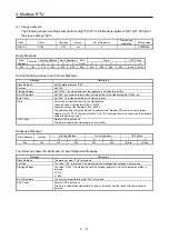
(1) Message frame
Query Message
Slave
Address Function
Starting Address No. of Registers
Byte
Count
Data
CRC Check
H
L
H
L
H
L
to
H
L
L
H
(8 bits)
10h
(8 bits) (8 bits) (8 bits) (8 bits) (8 bits) (8 bits) (8 bits)
to
(8 bits) (8 bits) (8 bits) (8 bits)
Message
Size
Description
Slave Address
8 bits
Set a station number to which the message is sent.
When "0" (station number for broadcast sending) is set, this message is sent to
all axes. (Note 1)
Function
8 bits
Set "10h".
Starting Address (Note 2)
16 bits
Set the start address of the holding registers to which data is written.
No. of Registers
16 bits
Set the number of points of data to write starting from the start address of the
holding registers to which data is written.
Set the number of write points described in the list of holding registers.
To write data in continuous registers, set a value obtained by adding the number
of write points of the target registers to this number.
Byte Count
8 bits
Set the size of the data to write.
Data (Note 2)
16 bits × n Set the data to write.
CRC Check
16 bits
Data for CRC error check
This data is calculated automatically by a controller.
Note 1. When the broadcast communication was performed, a Response Message is not returned from the slave. To send the next
Query Message continuously, send it considering the processing time of the slave. (Refer to section 4.6.)
2. Registers can be classified into two types: registers to which data can be continuously written and particular registers to which
data cannot be continuously written.
To write data in particular registers, write data in the target registers one by one.
For the details on whether data can be continuously written into the target registers or not, refer to chapter 7.
Response Message
Slave Address
Function
Starting Address
No. of Registers
CRC Check
H
L
H
L
L
H
(8 bits)
10h
(8 bits)
(8 bits)
(8 bits)
(8 bits)
(8 bits)
(8 bits)
Message
Size
Description
Slave Address
8 bits
The station number of a slave (servo amplifier) is returned.
Function
8 bits
When the Query Message was received without errors, "10h" is returned.
Starting Address
16 bits
The start address of the holding registers to which the data was written is
returned.
No. of Registers
16 bits
The number of points of written data starting from the start address of the holding
registers to which the data was written is returned.
CRC Check
16 bits
Data for CRC error check
This data is calculated automatically by a servo amplifier, and the result of the
calculation is returned.
Summary of Contents for MR-JE-C Series
Page 9: ...A 8 MEMO ...
Page 13: ...4 MEMO ...
Page 33: ...2 CC Link IE Field Network Basic SLMP 2 16 MEMO ...
Page 73: ...5 PARAMETERS 5 14 MEMO ...
Page 79: ...6 MANUFACTURER FUNCTIONS 6 6 MEMO ...
Page 143: ...MEMO ...


