MSM9225B User’s Manual
Chapter 3 Operational Description
3 – 3
3.1.3 Receive Procedure
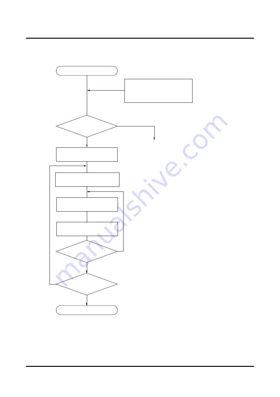
Figure 3-3 shows the receive procedure.
Receive procedure
YES
(MSM9225B)
Interrupt signal is generated when
reception is complete
INT
pin H to L
Set IRF bit of CANI register
(0Fhex) to 0
Verify received message box
number with TMN register (9Ehex)
Set RCS bit of message
control register (x0hex) to 0
Read receive data from
message box
Message
control register’s
RCS = 0?
CANC register’s (0Ehex)
CANA = 0?
Receive complete
YES
NO
YES
CANI
register’s (0Fhex)
IRF = 1?
NO
Check whether new receive data has
been written to the same message box
while data was being read.
NO
Check whether receive data has been written
to another message box while data was being read.
This step may be omitted and evaluation performed
based on the interrupt signal.
Verify that the interrupt has been caused
by the reception completion.
Processing of other interrupt causes
Figure 3-3 Receive Flowchart
INT
pin
Summary of Contents for MSM9225B
Page 7: ...Chapter 1 Overview...
Page 13: ...Chapter 2 Register Descriptions...
Page 53: ...Chapter 3 Operational Description...
Page 62: ...Chapter 4 Microcontroller Interface...
Page 71: ...Chapter 5 Electrical Characteristics...
Page 81: ...Appendixes...


