35
l
a
n
g
i
S
e
m
a
N
l
a
n
i
m
r
e
T
r
e
b
m
u
N
l
a
n
g
i
S
e
m
a
N
n
o
i
t
c
e
n
n
o
C
n
i
P
C
N
6
3
8
1
*
*
H
G
I
H
*
H
G
I
H
5
3
7
1
D
N
G
C
N
4
3
6
1
D
N
G
D
N
G
3
3
5
1
C
N
*
H
G
I
H
2
3
4
1
C
N
C
N
1
3
3
1
*
H
G
I
H
D
N
G
0
3
2
1
D
N
G
9
2
1
1
Y
S
U
B
8
2
0
1
K
C
A
7
2
9
7
D
6
2
8
6
D
5
2
7
5
D
4
2
6
4
D
3
2
5
3
D
2
2
4
2
D
1
2
3
1
D
0
2
2
0
D
9
1
1
E
B
O
R
T
S
The Specifications
of the Interface
Device control
Device control instructions are used to determine the communication sequence between the plotter and computer
through RS-232C interface and/or tell the plotter the current computer state. Among them, some device control
instructions set the output specifications of RD-GLI/II instructions.
Each device control instruction is organized with three letters: ESC (1Bh), “.” and one uppercase letter. Device
control instructions are of two types: one with parameters and the other without parameters.
Parameters can be omitted. A semicolon “;” is used as a delimiter to separate parameters if they are input in
succession. A “;” without parameters means that parameters were omitted.
If parameters are omitted, the default value is set. For a device control instruction with parameters, a terminator
needs to be input in order to signify the end of instructions. A colon “:” is used as the terminator which cannot be
omitted. Please refer to the following table for device control instructions. Depending on the instruction set that
has been selected, some device control instructions may be ignored.
List of device control instructions
36
.
.
.
.
.
.
.
.
.
.
.
.
.
.
.
.
19
18
.
.
.
.
.
.
.
.
.
.
.
.
.
.
.
.
1
: Compatible.
: Ignored.
25
.
.
.
.
.
.
.
.
.
.
14
13
.
.
.
.
.
.
.
.
.
.
.
1
l
a
n
g
i
S
N
e
m
a
l
a
n
i
m
r
e
T
r
e
b
m
u
N
l
a
n
g
i
S
N
e
m
a
n
o
i
t
c
e
n
n
o
C
n
i
P
C
N
5
2
3
1
C
N
C
N
4
2
2
1
C
N
C
N
3
2
1
1
C
N
C
N
2
2
0
1
C
N
C
N
1
2
9
C
N
R
T
D
0
2
8
C
N
C
N
9
1
7
G
S
C
N
8
1
6
R
S
D
C
N
7
1
5
S
T
C
D
X
R
.
S
6
1
4
S
T
R
C
N
5
1
3
D
X
R
D
X
T
.
S
4
1
2
D
X
T
1
G
F
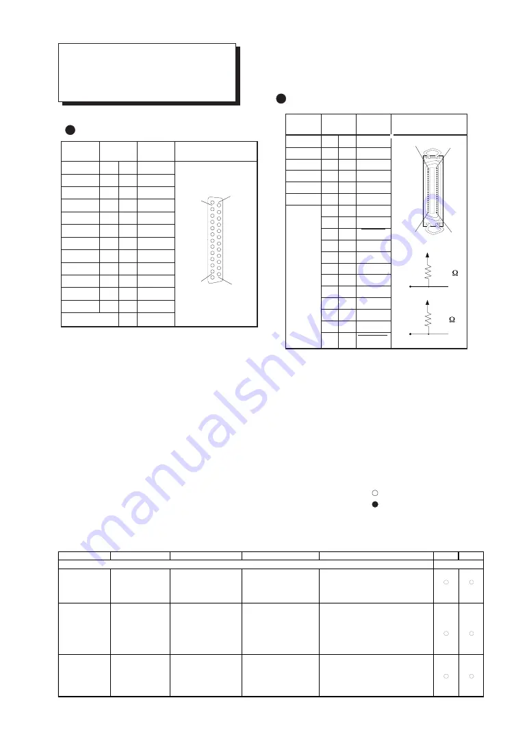
Serial Interface (RS-232C)
Connector
Parallel Interface (in compli-
ance with specifications of
Centronics)
Connector
+5V
+5V
* =
** =
Instruction
Format
Parameter
Range ([ ] is default)
Explanation
RD-GL I RD-GL II
Handshake Instructions
ESC .B
[ESC].B
None
Outputs the current remaining buffer capacity.
Output Remaining
Buffer Capacity
ESC .M
[ESC].M<P1>;<P2>;
P1:Delay time
0—32767(msec) [0(msec)]
Sets handshake output specifications.
Set Handshake
<P3>;<P4>;<P5>;<P6>: P2:Output trigger character
[0(Sets nothing)]
Output
P3:Echo terminator
[0(Sets nothing)]
Specifications (1)
P4:Output terminator
[13([CR])]
Note:When you specify some values to <P4> and
P5:Output terminator
[0]
<P5>, always set 0 to <P6>. When you specify
P6:Output initiator
[0(Sets nothing)]
some value to <P6>, always set 0 to <P5>.
ESC .N
[ESC].N<P1>;<P2>;
P1:Intercharacter delay
0-32767(msec) [0(msec)]
Sets an intercharacter delay, and also an Xoff
Set Handshake
<P3>;•••••;<P11>:
P2—P11
[All 0(Sets nothing)]
character for performing the Xon/Xoff handshake.
Output
:Xoff character (for Xon/Xoff)
Specifications (2)
Immediate response character
(for ENQ/ACK)
3.3K
100


