


RTD Embedded Technologies, Inc.
|
www.rtd.com
31
ERES35105
User’s Manual
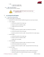
7.3.3
R
EADING
S
HIFT
R
EGISTER
S
TATUS
The Index Register includes a Read-Only bit indicating whether the shift register is busy. This can be accessed as follows:
1.
Read the GPIOAB_CTRL, GPIOCD_CTRL, SELECT and INDEX_DATA registers and store them so they can be restored.
2.
Read the Index/Status Register
a.
Set GPIOAB_CTRL and GPIOCD_CTRL to their Read values.
b.
Set SELECT such that DATA=0, WR_STRB=0, and OE#=0
c.
Read INDEX_DATA. Bit 8 is set if the Shift Register is busy, and cleared if the Shift Register is idle.
3.
Restore Other Registers
a.
Restore GPIOAB_CTRL
b.
Restore GPIOCD_CTRL bit-
wise or’ed with the Read Value (to ma
ke sure the SELECT pins are always output)
c.
Restore SELECT and INDEX_DATA with the WR_STRB bit cleared (to make sure a write isn’t duplicated)
NOTE: If multi-thread safe operation is not required, steps 1, and 3 can be
eliminated.
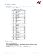
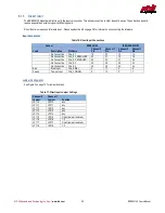
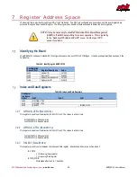
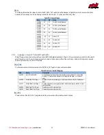
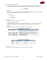
Board Registers
Table 26: Board Registers
Index
Data (16-bit)
0x00
BUILD_NUM_LS
0x01
BUILD_NUM_MS
0x02
Reserved
0x03
SR_SELECT
0x04
SR_DATA_OUT
0x05
SR_DATA_IN
0x06
CH0_SETUP_STATUS
0x07
CH1_SETUP_STATUS
0x08
CH0_POSITION
0x09
CH1_POSITION
7.4.1
BUILD_NUM_LS,
BUILD_NUM_MS
(R
EAD
-O
NLY
)
These two registers contain the build number of the EPLD. It can be used to track revisions of the EPLD. BUILD_NUM_LS is the least-
significant word, and BUILD_NUM_MS is the most significant word.
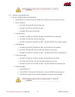
7.4.2
SR_SELECT
(R
EAD
/W
RITE
)
This register selects which of the various on-board devices the shift register is accessing. Possible options are below. All other values are
reserved.
0x00:
Channel 0 Mode
0x01:
Channel 0 Velocity Trim
0x02:
Channel 1 Mode
0x03:
Channel 1 Velocity Trim
0x04:
Excitation Frequency
0x05:
Excitation Amplitude


