background image

http://www.runzeliuti.com

15

The 1

st

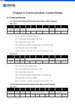
byte STX: frame header (CCH)

The 2

nd

byte ADDR: slave address (01H~ F7H)

The 3

rd

byte FUNC: function code

The 4-7

th

bytes: password of factory command

The 8

th

-11

th

bytes: parameters corresponding to the function code

The 12

th

byte ETX: end of frame (DDH)

The 13

th

-14

th

bytes: cumulative sum check code from byte 1 to 12

Byte return:

1

2

3

4

5

6

7

8

FH (Frame

header)

Address

code

State code

State parameters

EOF (End of

frame)

Cumulative sum

STX

ADDR

STATE

1-8 bit

9-16 bit

ETX

Low byte

High byte

The 1

st

byte STX: frame header (CCH)

The 2

nd

byte ADDR: slave address (01H~ F7H)

The 3

rd

byte STATE: state code

The 4-5

th

bytes: parameters corresponding to the state code

The 6

th

byte ETX: end of frame (DDH)

The 7

th

-8

th

bytes: cumulative sum check code from byte 1 to 6

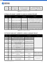
4.2 Setting Command (suitable for factory command format)

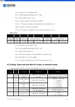
The password to set the command is AABBEEFFH (the lower one comes first).

Serial

number

FUNC

Code

Function

Parameter

Remark

1

00H

Set the device

address

00000001H-000000F7H

(1-247)

0x00 is broadcast address and it

only accepts, but does not reply.

2

01H

Set RS232 baud

rate

00000000H-00000004H

0:9600bps (Default)

1:19200bps
2:38400bps
3:57600bps

4:115200bps

3

02H

Set RS485 baud

rate

00000000H-00000004H

4

03H

Set suction angle

00000000H-00000E10H

(0-3600 degrees)

Default 36 degrees.

5

04H

Set direction

00000000H~00000001H

0:CCW

1:CW(Default)

Summary of Contents for LM60A

Page 1: ...http www runzeliuti com 1...

Page 2: ...4 Pump Head Tube Selection 6 2 5 Special Function Switching 7 Chapter 3 Keyboard Control Mode 8 3 1 Main Menu 8 3 2 Working Mode Description 8 3 2 1 Calibration Mode 8 3 2 2 Inquiry Mode 10 3 2 3 Sett...

Page 3: ...17 Chapter 5 External Control Mode 18 5 1 External Speed Control Operation 18 5 2 Maximum Speed Setting 19 Chapter 6 Technical Parameters of Peristaltic Pump Tube 20 6 1 Table of Commonly Used Flexibl...

Page 4: ...2 RS485 external control mode optional multiple signal conversion modules passive contact status output 1 2Product Features The product is composed of main machine pump head pump tube and other parts...

Page 5: ...ltiple speed control signal input external control mode only Direction signal input port Support steering switch control input external control mode only Start signal input port support start stop sig...

Page 6: ...Data 14 SWD CLK SWD Clock 15 ADC IN External speed signal input port 3 3V port Table 2 3 DB15 external terminal attribute definition 2 4 Pump Head Tube Selection Pump head Applicable tube Maximum flo...

Page 7: ...nction Switching 2 5 1 Restore factory settings Press and hold the edit key to turn on the machine 2 5 2 Chinese English language interface switching Press and hold the CW CCW key to turn on the machi...

Page 8: ...essage will be prompted and return to the main menu after three seconds If the input value is correct it will return to the main menu immediately after saving Press the Enter key if the edited value i...

Page 9: ...interface input the calibration speed and calibration time set the liquid volume to 0 and press the Enter key to save 3 Perform calibration process Press the CW CCW key select the required steering di...

Page 10: ...ch as standard speed standard flow minimum flow maximum flow and standard ratio can be queried 3 2 2 1 Calibrated speed Last calibrated speed value The default is 100 0 rpm 3 2 2 2 Standard flow After...

Page 11: ...enerally related to the pump head model pump tube model which generally does not need to be changed If the maximum speed is changed it is necessary to recalibrate and input the calibrated value correc...

Page 12: ...s disabled Inching in continuous mode the motor will run when the foot switch is stepped down and the motor will stop when it is released Linked in continuous mode when the foot switch is stepped down...

Page 13: ...lt Realize the function of waiting running 1 interval running 2 interval running n You can set the value of N N 0000 for infinite loop the maximum can be set to 9999 and you can also set the correspon...

Page 14: ...ive sum check code from byte 1 to 8 Byte return 1 2 3 4 5 6 7 8 9 10 FH Frame header Address code State code State parameters EOF End of frame Cumulative sum STX ADDR STATE 1 8 bit 9 16 bit 17 24 bit...

Page 15: ...1H F7H The 3rd byte STATE state code The 4 5th bytes parameters corresponding to the state code The 6th byte ETX end of frame DDH The 7th 8th bytes cumulative sum check code from byte 1 to 6 4 2 Setti...

Page 16: ...stability of the system Table 4 3 List of query command 4 4 Control command suitable for common command format Serial number FUNC Code Function Parameters Remarks 1 40H Take a few steps clockwise 0000...

Page 17: ...4 List of control command include the command of Query status 4 5 Communication Control Mode Interface 4 5 1 Control command example Figure 4 5 1 1 CW 0xC8 200 Steps Figure 4 5 1 2 CCW 0x190 400 Steps...

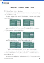
Page 18: ...ey to switch the type of external control signal The definition of adjusting speed signal code as follows Figure 5 1 3 when motor stops press up or down key to switch the type of signal 4 When the mot...

Page 19: ...ion module from 0 10V to 0 3 3V is required 3 4 20mA external speed control Special conversion module from 4 20mA to 0 3 3V is required 4 0 10KHz external speed control Special conversion module from...

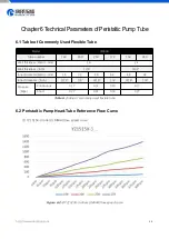
Page 20: ...4 Wall thickness Inch 1 16 3 32 Inner Diameter Metric mm 1 6 3 2 4 8 6 4 4 8 6 4 Inner Diameter Inch 1 16 1 8 3 16 1 4 3 16 1 4 Pressure Mpa Continuous 0 17 0 14 0 10 0 17 Short 0 27 0 24 0 14 0 27 T...

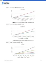
Page 21: ...Z1515X 6 rollers LM60A flow speed curve Figure 6 2 2 YZ1515X 6 rollers LM60A flow speed curve 3 YZ2515X 3 rollers LM60A flow speed curve Figure 6 2 3 YZ2515X 3 rollers LM60A flow speed curve 4 SN15 3...

Page 22: ...ve without any modification for reference only Note 2 The above test liquid is water and the test temperature is 25 Note 3 There are many factors affecting the actual test data such as the material an...

Page 23: ...rol part The backlight problem does not affect the normal use of the pump and the backlight function is generally used in a dark environment If it is a hardware failure it is recommended to return to...

Page 24: ...should be run for one or two minutes at a lower speed The maximum speed of the motor suitable for the pump head tube is exceeded Please refer to the above operation curve to select the reasonable spe...

Page 25: ...he maximum speed of the motor corresponding to the tube 3 Modify the expression of inquiry setting continuous mode 2020 02 28 V1 2 1 Delete commands with asterisk 2 Correct the use of RS232 interface...

Page 26: ...http www runzeliuti com 26 Chapter 9 Technical Service...

Reviews: