PulseBlasterDDS
The 10 individually controlled digital (TTL/CMOS) output bits are capable of delivering
±
25 mA per
bit and have an output voltage of 3.3V. These signals are available on the PC bracket-mounted DB-25
connector. Setting output bit 10 high via the output control word also resets the phase of the RF
waveforms for phase coherent switching, and can be used to generate a constant voltage on the
DACs.
Timing characteristics
PulseBlasterDDS’s timing controller can accept either an internal (on-board) crystal oscillator or
an external frequency source of up to 100 MHz. The innovative architecture of the timing controller
allows the processing of either simple timing instructions (delays of up to 2
32
= 4,294,967,296 clock
cycles), or double-length timing instructions (up to 2
52
clock cycles long – nearly 2 years with a 100
MHz clock!). Regardless of the type of timing instruction, the timing resolution remains constant for
any delay – just one clock period (e.g., 10 ns for a 100 MHz clock).
The timing controller has a very short minimum delay cycle – only nine clock periods. This
translates to a 90 ns minimum pulse/delay/update with a 100 MHz clock.
Phase Coherent Switching
The board allows for phase continuous and/or phase coherent switching. In addition, the DDS
can be reset to zero whenever a new RF pulse is started. Consult the explanation of the flags
parameter to the pb_inst instruction on page 12 for implementing the phase reset.
Instruction set
PulseBlasterDDS’ design features a set of commands for highly flexible program flow control. The
micro-programmed controller allows for programs to include branches, subroutines, and loops at up to
8 nested levels – all this to assist the user in creating dense pulse programs that cycle through
repetitious events, especially useful in numerous multidimensional spectroscopy and imaging
applications.
External triggering
PulseBlasterDDS can be triggered and/or reset externally via dedicated hardware lines. The two
separate lines combine the convenience of triggering (e.g., in cardiac gating) with the safety of the
"stop/reset" line. The required control signals are “active low” (or short to ground).
Status Readback
The status of the program can be read in hardware or software. The hardware status output
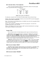
signals consist of five IDC connector pins labeled “Status”. The same output can be read through
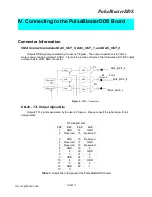
software using C. See section IV (Connecting to the PulseBlaster Board, page 16) for more detail
about the hardware lines and section III (Programming the PulseBlaster, page 11) for more detail
about the C function status_readback().
Summary
PulseBlasterDDS is a versatile, high-performance pulse/pattern TTL and RF/IF generator
operating at speeds of up to 100 MHz and capable of generating pulses/delays/intervals ranging from
90 ns to over 2 years per instruction. It can accommodate pulse programs with highly flexible control
commands of up to 32k program words. Its high-current output logic bits are independently controlled
with a voltage of 3.3 V. The output impedance of the analog channel is 50-ohms.
9/20/20057
www.spincore.com


