FPGA Registers
EPU-4562 Programmer’s Reference Manual
9
BIOS
AND
J
UMPER
S
TATUS
R
EGISTER
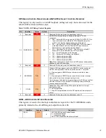
Table 5: SCR –Status/Control Register
Bit
Identifier
Access
Default
Description
7
BIOS_JMP
RO
N/A
Status of the external BIOS switch (jumper):
1 – Primary BIOS selected (the one on the COM Module)
0 – Backup BIOS selected (the one on the base board)
Note: For this implementation this reads the status of the jumper
all the time is essentially the “AND” of the jumper setting and (if
the BIOS_OR is set to a ‘1’) the BIOS_SEL setting. Note that if
BIOS_SEL sets a ‘1’ but a ‘0’ is read here then that means the
external jumper is installed.
6
BIOS_OR
R/W
0
BIOS Switch (jumper) Override
0 – BIOS Select will follow the BIOS_JMP switch setting (FPGA
BIOS_SEL setting has no affect)
1 – BIOS Select will follow the BIOS_SEL register setting
5
BIOS_SEL
R/W
0
BIOS Select (see BIOS_OR):
0 – Primary BIOS selected (the one on the COM Module)
1 – Backup BIOS selected (the one on the base board)
Note: If the external BIOS configuration jumper is set to Backup
then setting this will not have any affect. The jumper must not be
installed to use this selection mode. Must have BIOS_OR set to a
‘1’ for this to have any affect.
4
LED_DEBUG
R/W
0
Debug LED (controls the yellow LED):
0 – LED is off and follows its primary function (MSATA_DAS)
1 – LED is on
3
WORKVER
RO
N/A
Status used to indicate that the FPGA is not officially released
and is still in a working state.
0 – FPGA is released
1 – FPGA is in a working state (not released)
2
RESERVED
RO
N/A
Reserved. Writes are ignored; reads always return 0.
1
WP_JMP
RO
N/A
Back-up BIOS Write protect jumper status. WP_EN has to be set
to a ‘0’ to read the actual jumper.
0 – Jumper is installed (write-protect is enabled)
1 – Jumper is removed (not write protected)
0
WP_EN
R/W
0
Back-up BIOS Write protect control. It drives an open-drain
output.
0 – not write protected (open-drain output is Hi-Z so WP jumper
can be read)
1 – write protected (drives output low)

