EPU-4562 Programmer’s Reference Manual
41
Programming Information for Hardware
Interfaces
Watchdog Timer
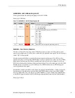
A Watchdog timer is implemented within the FPGA. When triggered, the Watchdog timer can set
a status bit, generate an interrupt and/or hit the push-button-reset. The Watchdog timer
implements a 1-255 second timeout.
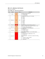
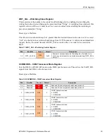
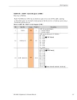
The Watchdog time out is set in an 8-bit register (WDT_VAL). When the Watchdog is enabled,
the WDT_VAL will start to count down. If the Watchdog is enabled and whenever WDT_VAL
is zero, the Watchdog is triggered (so a non-zero value must be written before enabling the
watchdog). Software must periodically write a non-zero value to WDT_VAL to prevent this
trigger. The value written should always be 1 greater than the desired timeout value due to a 0-1
second error band. Values written should be from 2-255 because a 1 could cause an immediate
trigger); that is, the actual timeout is WDT_VAL seconds with a -1 second to 0 second error
band.
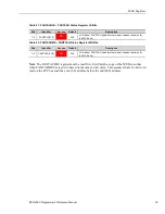
The Watchdog control/status register(s) have bits for the following:
Watchdog enable/disable (disabled by default)
Watchdog timeout status (This is cleared when the Watchdog is disabled or when a new
value is written to WDT_VAL. Writing WDT_VAL would be the interrupt-acknowledge.)
Watchdog interrupt IRQ select (from the same list of eight interrupts supported on the LPC
SERIRQ)
Interrupt enable
Board reset enable (when set, the board will be reset when the Watchdog timer expires).
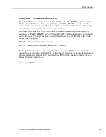
Programmable LED
User I/O connector J2 includes an output signal for attaching a software controlled LED.
Connect the cathode of the LED to J2, pin 16; connect the anode to +3.3 V. An on-board resistor
limits the current when the circuit is turned on. A programmable LED is provided on the
CBR-4005B paddleboard. Refer to the
VL-EPU-4562 Hardware Reference Manual
for the
location of the Programmable LED on the CBR-4005B paddleboard.
To switch the PLED on and off, refer to Table 3: PCR – Product Code and LED Register, on
page 8.
4

