background image

43

Error Handling

83

216014nn

LOG_CRIT

FuSa TiM510 wakeup error.

84

216095nn

LOG_CRIT

FuSa TiM510 stops by category 0.

85

216096nn

LOG_CRIT

FuSa TiM510 stops by category 2.

86

216051nn

LOG_ALERT

Cannot get the FuSa TiM510 parameter file.

87

216053nn

LOG_ALERT

FuSa TiM510 reads wrong value.

88

21605200

LOG_ALERT

There is no FuSa TiM510 extrinsic data.

89

21601100

LOG_ALERT

Cannot connect to the FuSa TiM510.

90

216012nn

LOG_ALERT

FuSa TiM510 parameters are not matched.

91

21601300

LOG_ALERT

FuSa TiM510 failed to initiate.

92

21716100

LOG_CRIT

FuSa etc board failed to read UDP.

93

21716200

LOG_ERR

FuSa etc board failed to send UDP.

94

217014nn

LOG_CRIT

FuSa etc board wakeup error.

95

217095nn

LOG_CRIT

FuSa etc board stops by category 0.

96

217096nn

LOG_CRIT

FuSa etc board stops by category 2.

97

217051nn

LOG_ALERT

Cannot get the FuSa, etc. board parameter file.

98

217053nn

LOG_ALERT

FuSa, etc. board reads wrong value.

99

21701100

LOG_ALERT

Cannot connect to the FuSa, etc. board.

100

217012nn

LOG_ALERT

FuSa etc board parameters are not matched.

101

21701300

LOG_ALERT

FuSa etc board failed to initiate.

102

21816100

LOG_CRIT

FuSa encoder board failed to read UDP.

103

21816200

LOG_ERR

FuSa encoder board failed to send UDP.

104

218014nn

LOG_CRIT

FuSa encoder board wakeup error.

105

218095nn

LOG_CRIT

FuSa encoder board stops by category 0.

106

218096nn

LOG_CRIT

FuSa encoder board stops by category 2.

107

218051nn

LOG_ALERT

Cannot get the FuSa encoder board parameter file.

108

218053nn

LOG_ALERT

FuSa encoder board reads wrong value.

109

21801100

LOG_ALERT

Cannot connect to the FuSa encoder board.

110

218012nn

LOG_ALERT

FuSa encoder board parameters are not matched.

111

21801300

LOG_ALERT

FuSa encoder board failed to initiate.

112

21905100

LOG_ALERT

Cannot get the button parameter file.

113

21905300

LOG_ALERT

Button reads wrong value.

114

22201300

LOG_ALERT

LED strip failed to initiate.

115

222051nn

LOG_ALERT

Cannot get the LED strip parameter file.

116

224022nn

LOG_ERR

Motor over current is detected.

117

224026nn

LOG_CRIT

Motor parameters are not matched.

118

22405100

LOG_ALERT

Cannot get the Motor parameter file.

119

22405300

LOG_ALERT

Motor reads wrong value.

120

30103100

LOG_ERR

SLAM cannot get available storage block.

121

30105100

LOG_ERR

Cannot get SLAM parameter file.

122

30105300

LOG_ERR

SLAM reads wrong value.

123

30105400

LOG_ERR

Cannot get SLAM parameter file to write.

124

30106400

LOG_ERR

SLAM failed to send map requesting.

125

30107300

LOG_ERR

SLAM has invalid argument.

Summary of Contents for GoCart250

Page 1: ...GoCart250 YUJIN AMS Service Manual Revision 1 4 Date 2023 03...

Page 2: ...ment Copyright and Disclaimer The information in this guide is subject to change without notice during the product s life cycle The printed version of the guide will be updated periodically Some detai...

Page 3: ...n the event of incorrect treatment they can harm human health and the environment For this reason do not dispose of your old device in the residual waste Instead use the collection point set up at you...

Page 4: ...14 The battery quantity is changed from 1ea to 2ea see 6 Replacing Battery on page 17 V1 2 05 11 2021 The chapter order of the document is rearranged The description is added and the image s resolutio...

Page 5: ...5 3 Replacing Electrical Components 14 5 4 Wiring Diagram 15 6 Replacing Battery 17 6 1 Replacing Battery on Rear of Robot 17 6 2 Front Battery Replacing 19 7 Replacing Sensor 22 7 1 Sensors Attached...

Page 6: ...CONNECTOR 30 8 2 UNIT SPEAKER ASSY 30 8 3 EMERGENCY_SWITCH_K22 87R N29 30 8 4 NEXT 306UHP_USB_HUB 30 8 5 LAN_NMC U610FZ_1M_LAN_CABLE 30 8 6 HDMI_ LS HDMI SMF 2M_HDMI_CABLE 31 8 7 UNIT_MIC_EIM001 31 8...

Page 7: ...is compliant with ISO 13482 PL d level safety to assure safety of the robot when operating in a public environment 1 2 About this Document This manual covers periodic maintenance and serviceable parts...

Page 8: ...damages Note Users must follow the instructions to avoid situations that could cause property damages 2 2 General Safety Warning During maintenance and repair the power to the docking station must be...

Page 9: ...9 Tools Required 3 Tools Required Item Picture Hex wrench set meter Power up Handle Adjustable wrench Screw Driver PH2 Table 1 Tools Required...

Page 10: ...chedule Fig 1 Product Part Information x2 3D Lidar x8 Cliff Sensor Tof x8 Sonar Sensor W238 x2 Window camera 3D RealSense x1 Window camera Astra Camera x1 Docking Terminal x4 Sonar Sensor HC SR04 x2 W...

Page 11: ...et cloth and make sure nothing is tangled in the wheels Replace as needed LiDAR Sensor Clean the cover of LiDAR sensor for best performance Do not use abrasive cleaning agents and careful not to scrat...

Page 12: ...acing Electrical Components 5 1 Disassembling Covers To replace electrical components remove covers to perform maintenance Fig 2 Disassemble Covers COVER_RIGHT_ASSY COVER_FRONT_ASSY COVER_LEFT_ASSY CO...

Page 13: ...lectrical components Refer to the figure below for more information Fig 3 Electrical Components Position PCB_FUSA_PWR_V001 LAN_HUB_ASSY SBC_ASSY_TOTAL MAGNETIC CONTACTOR MC 22b RELAY_RLY3_ASSY MOTOR_D...

Page 14: ...art 3 Replace the part with a new one To assemble the part proceed in the reverse order of those steps listed above Refer to Fig 4 Disassembly Direction of Components on page 14 for the disassembly di...

Page 15: ...circuit It shows the components of a circuit as simplified shapes and where fixtures and components may be connected to the system Also it shows how the electrical wires are interconnected between th...

Page 16: ...tery 1EA Direct Charging Brake Switch Cancel Switch 18 1 18 1 35 1 33 79 E stop Switch 19 1 Sperker R 34 3 Sperker L 34 2 FuSa LiDAR R C J5 J1 J10 J7 J9 J8 J2 1 4 10 5 67 1 1 36 37 FuSa LiDAR F R J5 J...

Page 17: ...1 On On Supply to both front and rear batteries 2 On Off Supply to front battery and Shut off to rear battery 3 Off On Shut off to front battery and Supply to rear battery 4 Off Off shut off both fron...

Page 18: ...t position Rear Battery Trigger Switch Rear right Position Fig 7 Turn off Main and Rear Battery Trigger Switch 4 Detach battery bracket by removing fixing bolts 2 ea Fig 8 Detach Battery Bracket 5 Unp...

Page 19: ...new battery then turn on the trigger switch and main switch 6 2 Front Battery Replacing 1 Open the battery cover on the rear of the robot by turning key counterclockwise Fig 10 Open Rear Cover 2 Turn...

Page 20: ...moving fixing bolts 2 ea Battery Bracket Fig 12 Detach Front Cover and Battery Bracket 6 First Unplug power cable connector on the right panel of battery Fig 13 Power Cable Connector on Right Panel 7...

Page 21: ...ctor For power supply Trigger Wire Harness red yellow For powering front battery RS 485 Wire Harness red blue Not Available Do not connect to robot 8 Take out by pulling the battery assembly 9 Insert...

Page 22: ...n reverse order 7 1 2 UNIT_WIFI_ANTENNA_ASSY 1 Disconnect the connector inside the frame 2 Release 2 screws 3 Pull down the unit to disassemble 4 Replace the unit with a new one by following the disas...

Page 23: ...4 screws 3 Pull up the unit to disassemble 4 Replace the unit with a new one by following the disassembly steps in reverse order 7 2 4 UNIT_CAMERA_ASSY 3D RealSense 1 Disconnect the connector to the...

Page 24: ...UNIT_DOCKING_TERMINAL 1 Disconnect the connector to the sensor 2 Release 4 screws 3 Pull up the unit to disassemble 4 Replace the unit with a new one by following the disassembly steps in reverse orde...

Page 25: ...e order 7 3 2 UNIT_SONAR_SENSOR W238 1 Disconnect the connector to the sensor 2 Release 4 screws 3 Pull up the unit to disassemble 4 Replace the unit with a new one by following the disassembly steps...

Page 26: ...verse order 7 4 2 UNIT_SONAR_SENSOR W238 1 Disconnect the connector to the sensor 2 Release 4 screws 3 Pull up the unit to disassemble 4 Replace the unit with a new one by following the disassembly st...

Page 27: ...order 7 5 2 UNIT_SONAR_SENSOR HC SR04 1 Disconnect the connector to the sensor 2 Release 4 screws 3 Pull up the unit to disassemble 4 Replace the unit with a new one by following the disassembly step...

Page 28: ...over bottom rear parts by removing 8 screws 2 Disconnect each of the 2 connectors of the sensor assembly that needs replacement 3 Release 4 screws 4 Pull up the unit to disassemble 5 Replace the unit...

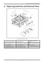
Page 29: ...rts CHARGER POWER CONNECTOR UNIT SPEAKER ASSY EMERGENCY_SWITCH_K22 87R N29 NEXT 306UHP_USB_HUB LAN_NMC U610FZ_1M_LAN_CABLE HDMI_ LS HDMI SMF 2M_HDMI_ CABLE UNIT_MIC_EIM001 SWITCH_MAIN_ASSY UNIT_OP_PAN...

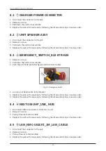
Page 30: ...e 3 Push the side hook like below figure and disconnect cables Fig 23 Emergency Switch 4 Loosen a nut fixed switch in the bracket 5 Replace the unit with a new one by following the disassembly steps i...

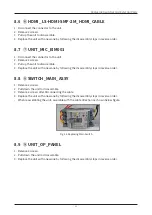
Page 31: ...4 Replace the unit with a new one by following the disassembly steps in reverse order 8 8 SWITCH_MAIN_ASSY 1 Release 2 screws 2 Pull down the unit to disassemble 3 Release 4 screws after Disconnecting...

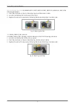
Page 32: ...eplace the unit with a new one by following the disassembly steps in reverse order Fig 25 Replacing Switches MODE_SWITCH_KEY_K22 61K For MODE_SWITCH_KEY_K22 61K_CSSD maintenance refer to the following...

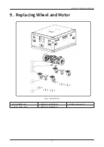
Page 33: ...33 Replacing Wheel and Motor 9 Replacing Wheel and Motor Fig 27 Wheels Parts MOTOR DRIVE ASSY WRENCH SCREW M6X16 CASTER_AVMU 110SF CASTER_AVMU_75RF WRENCH SCREW M8X20...

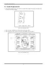
Page 34: ...can withstand the weight of the robot Place the side of the robot on the block carefully Fig 28 Caster Replacement 1 2 After removing SCREW from a caster replace it with a new caster 3 After replacing...

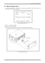
Page 35: ...m that can withstand the weight of the robot Place the front and rear of the robot on the blocks carefully Fig 30 Wheel Replacement 1 2 Remove COVER of WHEEL 3 Remove SCREW of WHEEL 4 After replacing...

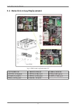
Page 36: ...ent Fig 32 Motor Drive Assy Replacement 1 MOTOR DRIVE ASSY WRENCH SCREW 6X16 WRENCH SCREW 8X12 MOTOR_R_Cable_power MOTOR_R_Cable_signal Motor_R_Brake_power Encoder_R_Connector MOTOR_L_Cable_power MOTO...

Page 37: ...t of the robot Place the side of the robot on the block carefully Fig 33 Motor Drive Assy Replacement 2 3 Remove the SCREW from the motor drive assembly 4 After replacing the motor drive assembly appl...

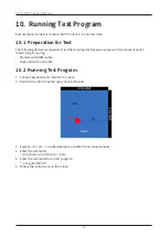
Page 38: ...wo adjacent walls 3 meters long for testing Monitor with HDMI cable Keyboard with usb cable 10 2 Running Test Program 1 Connect keyboard and monitor to a robot 2 Position the robot 3 meters away from...

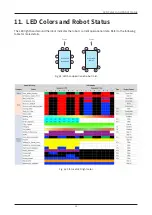
Page 39: ...ight band around the robot indicates the robot s current operational state Refer to the following table for more details 8 5 3 1 4 2 6 7 GoCart180 GoCart250 Front 1 4 2 3 7 6 8 5 GoCart200 Omni Front...

Page 40: ...or LOG_ERR The lowest priority Normal errors Keep its work after error becomes normal Publishing and Notifying error info Erro info time category sererity error code message LOG_CRIT Middle priority I...

Page 41: ...1200 LOG_CRIT 3D LiDAR horizontal mirror speed is out of range 20 20111300 LOG_CRIT 3D LiDAR vertical mirror speed is out of range 21 20111400 LOG_CRIT 3D LiDAR cannot get temperature data 22 20111500...

Page 42: ...rong value 60 20914100 LOG_CRIT Emergency stop button is presse 61 21001300 LOG_ALERT Battery failed to initiate 62 210051nn LOG_ALERT Cannot get the battery parameter file 63 210053nn LOG_ALERT Batte...

Page 43: ...led to read UDP 103 21816200 LOG_ERR FuSa encoder board failed to send UDP 104 218014nn LOG_CRIT FuSa encoder board wakeup error 105 218095nn LOG_CRIT FuSa encoder board stops by category 0 106 218096...

Page 44: ...ot make connection for pose manager 145 40306500 LOG_ERR Pose manager found mismatched size of transferred data 146 40402200 LOG_ALERT Local map got wrong map ID 147 40402600 LOG_ALERT Local map got i...

Page 45: ...n 175 50904200 LOG_ERR Motion integrator timed out 176 50909100 LOG_ERR Motion integrator detected potential collision 177 51002500 LOG_ERR Motion manager got empty data 178 51002700 LOG_ERR Motion ma...

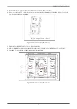
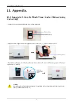
Page 46: ...Jig 2 Align the Marker Jig with the Charging Terminal on the charging station and then insert it 3 Peel off the adhesive side of the Visual Marker Sticker Attach the sticker to the empty space at the...

Page 47: ...Yujin Robot Co Ltd Harmony ro 187 beon gil 33 Yeonsu gu Incheon Songdo dong TEL 82 32 550 2300 FAX 82 32 550 2301 www yujinrobot com...

Reviews: