background image

232

ACS550-02/U2 User’s Manual

Embedded fieldbus

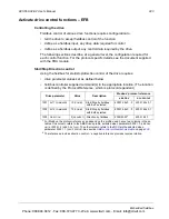
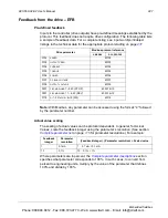
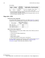
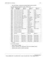
Mapping summary

The following table summarizes the mapping between the ACS550 (parameters and 

I/0) and Modbus reference space. For details, see 

Modbus addressing

 below.

Communication profiles

When communicating by Modbus, the ACS550 supports multiple profiles for control 

and status information. Parameter 5305 

EFB


CTRL


PROFILE

 selects the profile used.

ABB


DRV


LIM

 – The primary (and default) profile is the 

ABB


DRV


LIM

 profile. This 

implementation of the ABB Drives profile standardizes the control interface with 

ACS400 drives. The ABB Drives profile is based on the PROFIBUS interface. It is 

discussed in detail in the following sections.

DCU


PROFILE

 – The 

DCU


PROFILE

 profile extends the control and status interface to 

32 bits. It is the internal interface between the main drive application and the 

embedded fieldbus environment.

ABB


DRV


FULL

 – 

ABB


DRV


FULL

 is the implementation of the ABB Drives profile that 

standardizes the control interface with ACS600 and ACS800 drives. This 

implementation supports two control word bits not supported by the 

ABB


DRV


LIM


implementation.

Modbus addressing

With Modbus, each function code implies access to a specific Modbus reference set. 

Thus, the leading digit is not included in the address field of a Modbus message.

Note:

 The ACS550 supports the zero-based addressing of the Modbus 

specification. Holding register 40002 is addressed as 0001 in a Modbus message. 

Similarly, coil 33 is addressed as 0032 in a Modbus message.

Refer again to the 

Mapping summary

 above. The following sections describe, in 

detail, the mapping to each Modbus reference set.

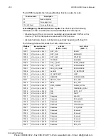
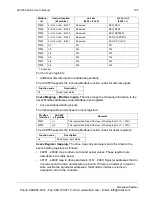
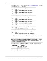
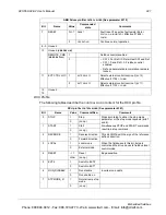
0xxxx Mapping – Modbus coils.

 The drive maps the following information to the 

0xxxx Modbus set called Modbus Coils:
• bit-wise map of the 

CONTROL


WORD

 (selected using parameter 5305 

EFB


CTRL


PROFILE

). The first 32 coils are reserved for this purpose. 

ACS550

Modbus reference

Supported function codes

• Control Bits
• Relay Outputs

Coils(0xxxx)

• 01 – Read Coil Status
• 05 – Force Single Coil
• 15 – Force Multiple Coils

• Status Bits
• Discrete Inputs

Discrete Inputs(1xxxx)

• 02 – Read Input Status

• Analog Inputs

Input Registers(3xxxxx)

• 04 – Read Input Registers

• Parameters
• Control/Status Words
• References

Holding Registers(4xxxx)

• 03 – Read 4X Registers
• 06 – Preset Single 4X Register
• 16 – Preset Multiple 4X Registers
• 23 – Read/Write 4X Registers

Phone: 800.894.0412 - Fax: 888.723.4773 - Web: www.clrwtr.com - Email: info@clrwtr.com

Summary of Contents for ACS550-02

Page 1: ...ACS550 User s Manual ACS550 02 Drives 132 355 kW ACS550 U2 Drives 250 550 hp Phone 800 894 0412 Fax 888 723 4773 Web www clrwtr com Email info clrwtr com ...

Page 2: ...pter Module User s Manual 3AFE64798693 English RPBA 01 PROFIBUS DP Adapter User s Manual 3AFE64504215 English Typical contents Safety Installation Programming Start up Diagnostics Technical data MAINTENANCE MANUALS Guide for Capacitor Reforming in ACS50 ACS55 ACS150 ACS350 ACS550 and ACH550 3AFE68735190 English The IndustrialIT wordmark and Product names in the form DriveIT are registered or pendi...

Page 3: ...550 02 U2 Drives 132 355 kW 250 550 hp User s Manual 3AFE64804626 Rev C EN EFFECTIVE 17 09 2007 2007 ABB Oy All Rights Reserved Phone 800 894 0412 Fax 888 723 4773 Web www clrwtr com Email info clrwtr com ...

Page 4: ...d electrician WARNING Even when the motor is stopped dangerous voltage is present at the power circuit terminals U1 V1 W1 and U2 V2 W2 and UDC UDC WARNING Dangerous voltage is present when input power is connected After disconnecting the supply wait at least 5 minutes to let the intermediate circuit capacitors discharge before removing the cover WARNING Even when power is switched off from the inp...

Page 5: ...rive will be damaged WARNING Do not control the motor with the disconnecting device disconnecting means instead use the control panel start and stop keys and or commands via the I O board of the drive The maximum allowed number of charging cycles of the DC capacitors i e power ups by applying power is five in ten minutes WARNING The ACS550 02 U2 is a field repairable drive In case of service or re...

Page 6: ... will overturn from a tilt of about 6 degrees Use extreme caution when manoeuvring a drive that runs on wheels An overturning drive can cause physical injury Note For more technical information contact the factory or your local ABB representative Do not tilt Phone 800 894 0412 Fax 888 723 4773 Web www clrwtr com Email info clrwtr com ...

Page 7: ... 23 Equipment connected to the motor cable 24 Selecting the control cables 26 Connection of a motor temperature sensor to the drive I O 27 Routing the cables 27 Installation Moving the drive 29 Before installation 31 Checking the insulation of the installation 35 Power cable connection diagram 36 Installation procedure 37 Installation checklist 59 Start up control with I O and ID Run How to start ...

Page 8: ...Planning 220 Mechanical and electrical installation EFB 220 Communication set up EFB 221 Activate drive control functions EFB 223 Feedback from the drive EFB 227 Diagnostics EFB 228 Modbus protocol technical data 231 ABB control profiles technical data 239 Fieldbus adapter Overview 251 Planning 253 Mechanical and electrical installation FBA 254 Communication set up FBA 255 Activate drive control f...

Page 9: ...y 301 Cooling 302 Dimensions weights and noise 302 Degrees of protection 302 Ambient conditions 303 Materials 304 Applicable standards 304 CE marking 305 C Tick marking 305 UL markings 305 IEC EN 61800 3 2004 Definitions 306 Compliance with the IEC EN 61800 3 2004 306 Equipment warranty and liability 307 Product protection in the USA 308 Dimension drawings 308 Contact ABB Product and service inqui...

Page 10: ... non operational for more than one year the drive DC link capacitors need to be reformed see Reforming on page 289 Check the installation site Installation Requirements for the installation site on page 33 Technical data Ambient conditions on page 303 Check the insulation of the motor and the motor cable Installation Checking the insulation of the installation on page 35 If the drive is about to b...

Page 11: ...is 1 6 2 I2hd of the drive in vector control and 0 2 I2hd in scalar control The control mode is selected by parameter 9904 MOTOR CTRL MODE 4 Consult the motor manufacturer before using a motor in a drive system where the motor nominal voltage differs from the AC power source voltage 5 Ensure that the motor insulation system withstands the maximum peak voltage in the motor terminals See section Req...

Page 12: ... bearing currents at voltages less than 500 V The common mode filter is composed of toroidal cores installed onto the output busbars inside the drive at the factory Requirements table The following table shows how to select the motor insulation system and when external du dt limitation and insulated N end non drive end motor bearings are required The motor manufacturer should be consulted regardin...

Page 13: ...tor insulated N bearing common mode filter Random wound ABB motors and generators of series HX_ and AM_ 0 UN 500 V Winding type Protective measures Enamelled wire with fibre glass taping insulated N bearing Form wound low voltage ABB motors of series AM_ and HX_ Protective measures insulated bearing construction common mode filter CMF Non ABB motors random wound and form wound windings Insulation ...

Page 14: ...fety of Machinery the disconnecting device must be one of the following types a switch disconnector of utilization category AC 23B EN 60947 3 a disconnector that has an auxiliary contact that in all cases causes switching devices to break the load circuit before the opening of the main contacts of the disconnector EN 60947 3 a circuit breaker suitable for isolation in accordance with EN 60947 2 US...

Page 15: ...rotection function that protects the motor and switches off the current when necessary Depending on a drive parameter value the function either monitors a calculated temperature value based on a motor thermal model or an actual temperature indication given by motor temperature sensors The user can tune the thermal model further by feeding in additional motor and load data The most common temperatu...

Page 16: ... breakers independent of the manufacturer hot ionized gases may escape from the breaker enclosure in case of a short circuit To ensure safe use special attention must be paid to the installation and placement of the breakers Follow the manufacturer s instructions Note Circuit breakers must not be used without fuses in the USA Ground fault protection The drive is equipped with an internal ground fa...

Page 17: ...der fault conditions so that the fault point voltage will not rise excessively when a ground fault occurs 600 V AC cable is accepted for up to 500 V AC covering the whole ACS550 range Symmetrical shielded cables must be used for the input and motor cables see the figure below A four conductor system cannot be used Compared to a four conductor system the use of symmetrical shielded cable reduces el...

Page 18: ...joint Bond the conduits also to the drive enclosure Use separate conduits for input power motor and control wiring Do not run motor wiring from more than one drive in the same conduit Armored cable shielded power cable The motor cables can be run in the same cable tray as other 460 V power wiring Control and signal cables must not be run in the same tray as power cables Six conductor 3 phases and ...

Page 19: ...capacitors in parallel with the three phase input of the drive 1 Do not connect a high power capacitor to the power line while the drive is connected The connection will cause voltage transients that may trip or even damage the drive 2 If capacitor load is increased decreased step by step when the AC drive is connected to the power line Ensure that the connection steps are low enough not to cause ...

Page 20: ...elding runs consistently without breaks from the drive to the motor Bypass connection WARNING Never connect the supply power to the drive output terminals U2 V2 and W2 If frequent bypassing is required employ mechanically connected switches or contactors Mains line voltage applied to the output can result in permanent damage to the drive Before opening a contactor sensorless vector control SVC mod...

Page 21: ...ission at switch off If not suppressed the disturbances may connect capacitively or inductively to other conductors in the control cable and form a risk of malfunction in other parts of the system Install the protective component as close to the inductive load as possible Do not install protective components at the control board terminal block 19 X1C 1 20 X1C 2 21 X1C 3 22 X1D 1 23 X1D 2 24 X1D 3 ...

Page 22: ...hielded cables Relay controlled signals providing their voltage does not exceed 48 V can be run in the same cables as digital input signals It is recommended that the relay controlled signals be run as twisted pairs Note Never mix 24 V DC and 115 230 V AC signals in the same cable Note Never ground control cables at both ends Relay cable The cable type with braided metallic screen e g ÖLFLEX by La...

Page 23: ...he relay from measuring circuit to output contact must be rated for the same voltage level as the main circuit of the drive Routing the cables Route the motor cable away from other cable routes Motor cables of several drives can be run in parallel installed next to each other It is recommended that the motor cable input power cable and control cables be installed on separate trays Avoid long paral...

Page 24: ...28 ACS550 02 U2 User s Manual Planning the electrical installation Phone 800 894 0412 Fax 888 723 4773 Web www clrwtr com Email info clrwtr com ...

Page 25: ...afety instructions can cause injury or death Note ACS550 U2 Installation Supplement 3AUA0000004067 English provides more information about the installation of ACS550 U2 drives Moving the drive Move the transport package by pallet truck to the installation site Unpack the package as shown below Lifting when the enclosure extension is included Phone 800 894 0412 Fax 888 723 4773 Web www clrwtr com E...

Page 26: ...prevent tilting They must be locked to the open position during the installation and always when wheeling the drive Do not wheel the drive except for installation the front direction is preferable because the front wheels are steadier The drive frame may be deformed if wheeled when the pedestal is removed If the drive is moved over long distances place it on its back on a pallet and move it by for...

Page 27: ...mage Before attempting installation and operation check the information on the type designation label of the drive to verify that the drive is of the correct type Drive identification Drive labels To determine the type of drive you are installing refer to either serial number label attached inside the drive or type code label attached under the front visor Phone 800 894 0412 Fax 888 723 4773 Web w...

Page 28: ...al number shown on the labels is described below Serial number is of format CYYWWXXXXX where C Country of manufacture YY Year of manufacture WW Week of manufacture 01 02 03 for week 1 week 2 week 3 XXXXX Integer starting every week from 0001 AC Standard Drive 550 product series Construction region specific Output current rating Voltage rating Options Examples of options 0J400 No control panel J404...

Page 29: ... non flammable Check that there is nothing on the wall to inhibit the installation If the drive is mounted on the wall the wall must be as close to vertical as possible and strong enough to carry the weight of the drive The drive must not be installed without the pedestal on the wall Free space around the drive See section Choose the mounting orientation a b or c on page 37 Cooling air flow Provid...

Page 30: ...or on IT ungrounded and corner grounded TN systems frame size R8 on page 46 WARNING If a drive with its EMC filter frame size R7 or varistor frame sizes R7 and R8 connected is installed on an IT system an ungrounded power system or a high resistance grounded over 30 ohm power system the system will be connected to earth potential through the EMC filter capacitors or varistor This may cause danger ...

Page 31: ...otor and motor cable Check the insulation of the motor and motor cable as follows 1 Check that the motor cable is connected to the motor and disconnected from the drive output terminals U2 V2 and W2 2 Measure the insulation resistance between each phase conductor and the Protective Earth conductor using a measuring voltage of 500 V DC The insulation resistance of an ABB motor must exceed 10 Mohm r...

Page 32: ...ear 2 Used if the conductivity of the cable shield is 50 of the conductivity of the phase conductor 3 For minimum radio frequency interference at the motor end ground the cable shield 360 degrees at the lead through of the motor terminal box or ground the cable by twisting the shield as follows flattened width 1 5 length In the figure below b 1 5 a 360 degrees grounding Conductive gaskets a b Grou...

Page 33: ...ace 2 Mark the locations for the two fixing points in the wall 3 Mark the bottom edges of the drive to the floor Frame size Mounting orientation Required free space around the drive for mounting maintenance service and cooling Front Side Above mm in mm in mm in R7 a 500 20 200 7 9 b 500 20 200 7 9 c 200 7 9 lifting space lifting space R8 a 600 24 300 12 b 600 24 300 12 c 300 12 lifting space lifti...

Page 34: ...he pedestal is constructed normally on site 1 Check that there is a place for the fixing holes 2 Check that the route is free for the main cables Preparing the mounting location against a wall Because of its weight it is not recommended to mount the drive on a wall but it can be fastened on a wall for additional support 1 Lift the drive against the wall into the mounting place 2 Check that the cab...

Page 35: ...ws 2 Undo the red screws that fix the pedestal to the frame from front 3 Undo the red M8 combi screws 6 pcs that connect the busbars of the pedestal to the upper frame Use a torque wrench with an extension bar 4 Wheel the frame out by using the handle 1 1 Wheeling the frame out 2 4 3 3 3 3 3 3 Phone 800 894 0412 Fax 888 723 4773 Web www clrwtr com Email info clrwtr com ...

Page 36: ...same way The legs will prevent the drive from falling down during the installation 3 Undo the screws that fix the pedestal to the frame from front 4 Undo the screws that connect the busbars of the pedestal to the upper frame Use a torque wrench with an extension see the figure on page 41 5 Wheel the drive frame out by using the handle see the figure on page 41 1 1 3 2 3 2 Phone 800 894 0412 Fax 88...

Page 37: ...ACS550 02 U2 User s Manual 41 Installation Pedestal disconnected 5 4 Red M10 combi screws Phone 800 894 0412 Fax 888 723 4773 Web www clrwtr com Email info clrwtr com ...

Page 38: ...eading the control cables through the lead through plate on page 49 and fasten the plate to the floor after that if the cabling procedure is more convenient in that way Note These screws bolts are also used to fix the pedestal to the lead through plate so you will have to remove and refasten them later on when the pedestal is fixed These brackets can be removed for the duration of the installation...

Page 39: ...ove the EMC screen by undoing the five fastening screws Note The screen must be replaced when the cables have been connected Tightening torque of the fastening screws is 5 N m 3 7 lbf ft EMC screen W2 V2 U2 UDC PE UDC R Frame size R7 Phone 800 894 0412 Fax 888 723 4773 Web www clrwtr com Email info clrwtr com ...

Page 40: ...ounded over 30 ohm power system the system will be connected to earth potential through the EMC filter capacitors This may cause danger or damage the drive If a drive with its EMC filter connected is installed on a corner grounded TN system the drive will be damaged Only frame size R7 drives have an EMC filter 1 Disconnect the EMC filter by removing the two screws shown in the figure below Phone 8...

Page 41: ...ohm power system the system will be connected to earth potential through the varistor This may cause danger or damage the drive If a drive with its varistor connected is installed on a corner grounded TN system the drive will be damaged 1 Ensure that the power is removed from the drive 2 Remove the upper front cover by undoing the screws 3 Disconnect the varistor cable 4 Fasten the front cover 3 P...

Page 42: ... be connected to earth potential through the varistor This may cause danger or damage the drive If a drive with its varistor connected is installed on a corner grounded TN system the drive will be damaged 1 Ensure that the power is removed from the drive 2 Remove the upper front cover by undoing the screws 3 Disconnect the varistor cable from the board 4 Disconnect the other end of the varistor ca...

Page 43: ... adequate length Put the pedestal onto the lead through plate and check the length of the conductors Remove the pedestal 5 Crimp or screw cable lugs onto the conductors WARNING The maximum allowed width of the cable lug is 38 mm 1 5 in Wider cable lugs may cause a short circuit 6 Connect the twisted shields of the cables to the PE terminal frame size R7 or to the grounding clamps or PE terminal fr...

Page 44: ...inal U1 U2 V1 V2 W1 W2 A hole 1 mm in 159 6 3 262 10 3 365 14 4 A hole 2 mm in 115 4 5 218 8 5 321 12 6 PE terminal hole 1 2 3 4 5 6 B mm in 43 1 7 75 3 0 107 4 2 139 5 5 171 6 7 203 8 0 Phone 800 894 0412 Fax 888 723 4773 Web www clrwtr com Email info clrwtr com ...

Page 45: ...and slide the grommets onto the cables Terminal A B A B Hole 1 Hole 2 Hole 3 Hole 1 Hole 2 Hole 3 mm mm mm mm in in in in Frame size R8 U1 432 387 342 40 17 0 15 2 13 5 1 6 V1 148 5 8 W1 264 10 4 U2 284 239 194 40 11 2 9 4 7 6 1 6 V2 148 5 8 W2 264 10 4 PE terminal hole 1 2 3 4 5 6 7 8 9 C mm in 24 0 9 56 2 2 88 3 5 120 4 7 152 6 0 184 7 2 216 8 5 248 9 8 280 11 0 PE Phone 800 894 0412 Fax 888 723...

Page 46: ...me size R7 Fasten the EMC screen between the input and motor cables as shown in the figure on page 43 WARNING It is not allowed to connect the cables directly to the drive module terminals The lead through insulation material is not strong enough to carry the mechanical stress exerted by the cables The cable connections must be performed in the pedestal 7 Wheel the drive frame back on the pedestal...

Page 47: ... Fasten the drive with screws or bolts to the holes in the wall Note In mounting orientation a see page 37 do not fasten the drive to a wall if it is subjected to sideways vibration 5 Connect the control cables as described in section Connecting the control cables on page 54 Fastening the covers 1 Connect the control panel cables 2 Fasten the upper front cover 3 Fasten the lower front covers Termi...

Page 48: ...e pedestal connected to the frame Remove the lead through plate and the lower front and side plates Lift the drive frame onto the lead through plate from above Fasten the drive to the floor Connect the cable lugs to the terminals Fasten the lower front and side plates Fasten the drive by top to the wall recommended Phone 800 894 0412 Fax 888 723 4773 Web www clrwtr com Email info clrwtr com ...

Page 49: ...able ties to these holes Secure the cables with cable ties to the holes in the capacitor pack frame Lead the cables through the cushions This is for mechanical support only No 360 degrees EMC grounding is needed here Frame size R7 Frame size R8 Phone 800 894 0412 Fax 888 723 4773 Web www clrwtr com Email info clrwtr com ...

Page 50: ...N m 0 3 lbf ft torque for both frame sizes Control connections To complete the control connections use Cable recommendations in section Power factor compensation capacitors on page 23 Table Hardware description on page 55 ABB Standard macro on page 102 Complete parameter descriptions on page 128 Embedded fieldbus Mechanical and electrical installation EFB on page 220 Phone 800 894 0412 Fax 888 723...

Page 51: ...cted internally to chassis gnd through 1 MΩ 10 24V Auxiliary voltage output 24 V DC 250 mA reference to GND Short circuit protected 11 GND Auxiliary voltage output common Connected internally as floating 12 DCOM Digital input common To activate a digital input there must be 10 V or 10 V between that input and DCOM The 24 V may be provided by the ACS550 X1 10 or by an external 12 24 V source of eit...

Page 52: ...y a proper factory grounding The terminals on the control board as well as on the optional modules attachable to the board fulfill the Protective Extra Low Voltage PELV requirements stated in EN 50178 provided that the external circuits connected to the terminals also fulfill the requirements and the installation site is below 2000 m 6562 ft You can wire the digital input terminals in either a PNP...

Page 53: ...or ground it indirectly via a few nanofarads high frequency high voltage capacitor e g 3 3 nF 3000 V The shield can also be grounded directly at both ends if they are in the same ground line with no significant voltage drop between the end points Keep the signal wire pairs twisted as close to the terminals as possible Twisting the wire with its return wire reduces disturbances caused by inductive ...

Page 54: ...ule slot of the control board See the appropriate optional module manual for cable connections Cabling of I O and fieldbus modules Set according to the supply voltage 380 V 400 V 415 V 440 V 480 V Set to 220 V if the supply frequency is 60 Hz The voltage is set to 230 V 50 Hz at the factory Shield Module 2 3 4 1 Grounding wire of the outer shield Strain relief with a cable tie Alternative to a a S...

Page 55: ... ungrounded and corner grounded TN systems frame size R7 only on page 44 Disconnecting the varistor on IT ungrounded and corner grounded TN systems frame size R7 on page 45 Disconnecting the varistor on IT ungrounded and corner grounded TN systems frame size R8 on page 46 The capacitors are reformed if stored over one year See Reforming on page 289 The drive is grounded properly The input power vo...

Page 56: ...hrough all essential settings to be done In the limited start up the drive gives no guidance you go through the very basic settings by following the instructions given in the manual If you have a Basic Control Panel follow the instructions given in section How to perform the limited start up on page 61 How to perform the limited start up For the limited start up you can use the Basic Control Panel...

Page 57: ...lete parameter descriptions starting on page 128 The general parameter setting procedure is described below for the Basic Control Panel You find more detailed instructions for the Basic Control Panel on page 97 Instructions for the Assistant Control Panel are on page 79 The general parameter setting procedure 1 To go to the Main menu press if the bottom line shows OUTPUT otherwise press repeatedly...

Page 58: ...e as on the motor nameplate For example if the motor nominal speed is 1470 rpm on the nameplate setting the value of parameter 9908 MOTOR NOM SPEED to 1500 rpm results in the wrong operation of the drive motor nominal voltage parameter 9905 motor nominal current parameter 9906 Allowed range 0 2 2 0 I2hd A motor nominal frequency parameter 9907 motor nominal speed parameter 9908 motor nominal power...

Page 59: ...n to step DIRECTION OF THE MOTOR ROTATION on page 64 IDENTIFICATION MAGNETIZATION WITH ID RUN SELECTION 0 OFF IDMAGN As stated above the identification magnetization is performed only if parameter 9904 is set to 1 VECTOR SPEED or 2 VECTOR TORQ or parameter 9904 is set to 3 SCALAR FREQ and parameter 2101 is set to 3 SCALAR FLYST or 5 FLY BOOST Press key to switch to local control LOC shown on the l...

Page 60: ...Set also deceleration time 2 parameter 2206 if two deceleration times will be used in the application SAVING A USER PARAMETER SET AND FINAL CHECK The start up is now completed However it might be useful at this stage to set the parameters required by your application and save the settings as a user parameter set as instructed in section User parameter sets on page 111 Check that the drive state is...

Page 61: ...ant Press if you do not want to run the Start up Assistant Press key to highlight and then press if you want to make the panel ask or not ask the question about running the Start up Assistant again the next time you switch on the power to the drive SELECTING THE LANGUAGE If you decided to run the Start up Assistant the display then asks you to select the language Scroll to the desired language wit...

Page 62: ...CK The start up is now completed However it might be useful at this stage to set the parameters required by your application and save the settings as a user parameter set as instructed in section User parameter sets on page 111 After the whole set up is completed check there are no faults or alarms shown on the display and the panel LED is green and does not blink The drive is now ready for use OK...

Page 63: ...control In remote control the panel display shows text REM STARTING AND CONTROLLING THE SPEED OF THE MOTOR Start by switching digital input DI1 on Assistant Control Panel The arrow starts rotating It is dotted until the setpoint is reached Basic Control Panel Text FWD starts flashing fast and stops after the setpoint is reached Regulate the drive output frequency motor speed by adjusting the volta...

Page 64: ...rameter setting procedure is not repeated here For Assistant Control Panel see page 79 and for Basic Control Panel page 97 in chapter Control panels PRE CHECK WARNING The motor will run at up to approximately 50 80 of the nominal speed during the ID Run The motor will rotate in the forward direction Ensure that it is safe to run the motor before performing the ID Run De couple the motor from the d...

Page 65: ...PANEL Change parameter 9910 ID RUN to 1 ON Save the new setting by pressing If you want to monitor actual values during the ID Run go to the Output mode by pressing repeatedly until you get there Press to start the ID Run The panel keeps switching between the display that was shown when you started the ID Run and the alarm display presented on the right In general it is recommended not to press an...

Page 66: ...mmed assistants to automate the most common parameter setups The panel provides language support It is available with different language sets Compatibility The manual is compatible with the following panel versions Basic Control Panel ACS CP C Rev K Assistant Control Panel Area 1 ACS CP A Rev Y Assistant Control Panel Area 2 ACS CP L Rev E Assistant Control Panel Asia ACS CP D Rev M See page 75 fo...

Page 67: ...nd if enabled the clock display 3 Soft key 1 Function depends on the context The text in the lower left corner of the LCD display indicates the function 4 Soft key 2 Function depends on the context The text in the lower right corner of the LCD display indicates the function 5 Up Scrolls up through a menu or list displayed in the center of the LCD display Increments a value if a parameter is select...

Page 68: ...ight modes is described in this chapter When a fault or alarm occurs the panel goes automatically to the Fault mode showing the fault or alarm You can reset it in the Output or Fault mode see chapter Diagnostics No Field Alternatives Significance 1 Control location LOC Drive control is local that is from the control panel REM Drive control is remote such as the drive I O or fieldbus 2 State Forwar...

Page 69: ...tion Output 77 How to set the speed frequency or torque reference Output 78 How to change the value of a parameter Parameters 79 How to select the monitored signals Parameters 80 How to do guided tasks specification of related parameter sets with assistants Assistants 81 How to view and edit changed parameters Changed Parameters 84 How to view faults Fault Logger 85 How to reset faults and alarms ...

Page 70: ...irmware version ROM CRC panel ROM check sum Flash Rev flash content version Flash content comment When you release the key the panel goes to the Output mode 01 OPERATING DATA 03 FB ACTUAL SIGNALS 04 FAULT HISTORY 10 START STOP DIR 11 REFERENCE SELECT PAR GROUPS 10 EXIT SEL 00 00 LOC EXIT 00 00 This group defines external sources EXT1 and EXT2 for commands that enable start stop and HELP LOC EXIT 0...

Page 71: ...he drive using the control panel press The result depends on how long you press the key If you release the key immediately the display flashes Switching to the local control mode the drive stops Set the local control reference as instructed on page 78 If you press the key for about two seconds the drive continues as before The drive copies the current remote values for the run stop status and the ...

Page 72: ...nge the direction of the motor rotation Step Action Display 1 If you are not in the Output mode press repeatedly until you get there 2 If the drive is in remote control REM shown on the status line switch to local control by pressing The display briefly shows a message about changing the mode and then returns to the Output mode 3 To change the direction from forward shown on the status line to rev...

Page 73: ...ference value shown in the top right corner of the display press The value changes immediately It is stored in the drive permanent memory and restored automatically after power switch off To decrease the value press Step Action Display 1 If you are not in the Output mode press repeatedly until you get there 2 To increase the contrast press keys and simultaneously To decrease the contrast press key...

Page 74: ...keys simultaneously replaces the displayed value with the default value 6 To save the new value press To cancel the new value and keep the original press MENU EXIT PARAMETERS ASSISTANTS CHANGED PAR EXIT ENTER 00 00 MAIN MENU 1 LOC ENTER 01 OPERATING DATA 03 FB ACTUAL SIGNALS 04 FAULT HISTORY 10 START STOP DIR 11 REFERENCE SELECT EXIT SEL 00 00 PAR GROUPS 01 LOC 99 START UP DATA 01 OPERATING DATA 0...

Page 75: ...ify the decimal point location or use the decimal point location and unit of the source signal setting 9 DIRECT For details see parameter 3404 Signal 1 parameter 3404 OUTPUT1 DSP FORM Signal 2 parameter 3411 OUTPUT2 DSP FORM Signal 3 parameter 3418 OUTPUT3 DSP FORM 3 Select the units to be displayed for the signals This has no effect if parameter 3404 3411 3418 is set to 9 DIRECT For details see p...

Page 76: ...you through the task of specification of its parameter set as shown in steps 4 and 5 below After that you can select another assistant on the Assistants menu or exit the Assistants mode The Motor Set up Assistant is used here as an example If you select the Start up Assistant it activates the first assistant which guides you through the task of specification of its parameter set as shown in steps ...

Page 77: ...06 If AI1 is used Setting analog input AI1 limits scale inversion 1301 1303 3001 Setting the reference limits 1107 1108 Torque control Selecting the source for the torque reference 1106 If AI1 is used Setting analog input AI1 limits scale inversion 1301 1303 3001 Setting the reference limits 1107 1108 Setting the torque ramp up and ramp down times 2401 2402 PID control Selecting the source for the...

Page 78: ...Setting the current and torque limits 2003 2017 Output signals Selecting the signals indicated through relay output RO Group 14 RELAY OUTPUTS Selecting the signals indicated through analog output AO Setting the minimum maximum scaling and inversion Group 15 ANALOG OUTPUTS Name Description Set parameters Phone 800 894 0412 Fax 888 723 4773 Web www clrwtr com Email info clrwtr com ...

Page 79: ... value for the parameter with keys and Pressing the key once increments or decrements the value Holding the key down changes the value faster Pressing the keys simultaneously replaces the displayed value with the default value 5 To accept the new value press If the new value is the default value the parameter is removed from the list of changed parameters To cancel the new value and keep the origi...

Page 80: ...R on the menu with keys and and pressing The display shows the fault log starting with the latest fault The number on the row is the fault code according to which the causes and corrective actions are listed in chapter Diagnostics 3 To see the details of a fault select it with keys and and press 4 To show the help text press Scroll the help text with keys and After reading the help press to return...

Page 81: ...VISIBLILITY on the menu press select Show clock Hide clock and press or if you want to return to the previous display without making changes press To specify the date format select DATE FORMAT on the menu press and select a suitable format Press to save or to cancel your changes To specify the time format select TIME FORMAT on the menu press and select a suitable format Press to save or to cancel ...

Page 82: ...g which daylight saving time is used in each country or area whose daylight saving changes you can select to be followed To disable automatic clock transitions according to the daylight saving changes select Off and press To enable automatic clock transitions select the country or area whose daylight saving changes are followed and press To return to the previous display without making changes pre...

Page 83: ...om the control panel to the drive DOWNLOAD FULL SET This writes all parameters including the internal non user adjustable motor parameters to the drive It does not include the user sets of parameters Note Only use this function to restore a drive from a backup or to transfer parameters to systems that are identical to the original system copy a partial parameter set part of the full set from the c...

Page 84: ...he completion Press to return to the Par Backup menu To perform downloads select the appropriate operation here DOWNLOAD FULL SET is used as an example on the Par Backup menu with keys and and press The display shows the transfer status as a percentage of completion Press if you want stop the operation After the download is completed the display shows a message about the completion Press to return...

Page 85: ...cates a decimal point e g 4A6 means 4 6 A Y 2 200 V 4 400 V 6 600 V Z i European loading package n US loading package FIRMWARE firmware version of the drive You can scroll the information with keys and 4 Press to return to the Par Backup menu MENU EXIT PARAMETERS ASSISTANTS CHANGED PAR EXIT ENTER 00 00 MAIN MENU 1 LOC ENTER UPLOAD TO PANEL BACKUP INFO DOWNLOAD FULL SET DOWNLOAD APPLICATION DOWNLOA...

Page 86: ...eys and and press After a brief pause the display shows the current settings for the selection 4 Select the setting line with a parameter number with keys and and press 5 Specify a new value for the setting with keys and Pressing the key once increments or decrements the value Holding the key down changes the value faster Pressing the keys simultaneously replaces the displayed value with the defau...

Page 87: ...tion Flashing slowly stopped Flashing rapidly running not at setpoint Steady running at setpoint Displayed value can be modified in the Parameter and Reference modes 2 RESET EXIT Exits to the next higher menu level without saving changed values Resets faults in the Output and Fault modes 3 MENU ENTER Enters deeper into menu level In the Parameter mode saves the displayed value as the new setting 4...

Page 88: ...between local and remote control and monitor up to three actual values one at a time To do other tasks go first to the Main menu and select the appropriate mode How to do common tasks The table below lists common tasks the mode in which you can perform them and the page number where the steps to do the task are described in detail Task Mode Page How to switch between local and remote control Any 9...

Page 89: ...immediately the display flashes LoC the drive stops Set the local control reference as instructed on page 96 If you press the key for about two seconds release when the display changes from LoC to LoC r the drive continues as before The drive copies the current remote values for the run stop status and the reference and uses them as the initial local control settings To stop the drive in local con...

Page 90: ... signal The unit is shown on the right Page 98 tells how to select up to three signals to be monitored in the Output mode The table below shows how to view them one at a time How to browse the monitored signals Step Action Display 1 If more than one signals have been selected to be monitored see page 98 you can browse them in the Output mode To browse the signals forward press key repeatedly To br...

Page 91: ...ly shows LoC before switching to local control Note With Group 11 REFERENCE SELECT you can allow the reference modification in remote control REM 3 If the panel is not in the Reference mode rEF not visible press key or until you see rEF and then press Now the display shows the current reference value with under the value 4 To increase the reference value press To decrease the reference value press...

Page 92: ...d parameter group 4 Press The display shows one of the parameters in the selected group 5 Use keys and to find the desired parameter 6 Press and hold for about two seconds until the display shows the value of the parameter with underneath indicating that changing of the value is now possible Note When is visible pressing keys and simultaneously changes the displayed value to the default value of t...

Page 93: ...ed and only the signal specified by 3408 appears in the display If all three parameters are set to 0 i e no signals are selected for monitoring the panel displays text n A 2 Specify the decimal point location or use the decimal point location and unit of the source signal setting 9 DIRECT Bar graphs are not available for Basic Operation Panel For details see parameter 3404 Signal 1 parameter 3404 ...

Page 94: ... to the original system copy a partial parameter set from the control panel to a drive dL P Download Partial The partial set does not include user sets internal motor parameters parameters 9905 9909 1605 1607 5201 nor any Group 51 EXT COMM MODULE and Group 53 EFB PROTOCOL parameters The source and target drives and their motor sizes do not need to be the same copy USER S1 parameters from the contr...

Page 95: ...sing repeatedly until you see MENU at the bottom 2 If the panel is not in the Copy mode CoPY not visible press key or until you see CoPY Press 3 To upload all parameters including user sets from the drive to the control panel step to uL with keys and Press During the transfer the display shows the transfer status as a percentage of completion To perform downloads step to the appropriate operation ...

Page 96: ...roup 53 EFB PROTOCOL parameters Group 29 MAINTENANCE TRIG parameters After selecting a macro you can make additional parameter changes manually with the control panel You enable application macros by setting the value for parameter 9902 APPLIC MACRO By default 1 ABB STANDARD is the enabled macro The following sections describe each of the application macros and provide a connection example for eac...

Page 97: ...rt Stop Activate to start Fwd Rev Activate to reverse rotation direction Constant speed selection2 Constant speed selection2 Ramp pair selection Activate to select 2nd acc dec ramp pair Relay output 1 programmable Default operation Relay output 2 programmable Default operation Relay output 3 programmable Default operation Note 1 The external reference is used as a speed reference if a vector mode ...

Page 98: ... voltage 10 V DC Motor output speed 0 20 mA Constant speed selection1 Constant speed selection1 Relay output 1 programmable Default operation Relay output 2 programmable Default operation Relay output 3 programmable Default operation Output current 0 20 mA Ready 19 connected to 21 Running 22 connected to 24 Fault 1 25 connected to 27 Analog input circuit common Not used Analog output circuit commo...

Page 99: ...r output speed 0 20 mA Constant speed selection1 Constant speed selection1 Relay output 1 programmable Default operation Relay output 2 programmable Default operation Relay output 3 programmable Default operation Output current 0 20 mA Ready 19 connected to 21 Running 22 connected to 24 Fault 1 25 connected to 27 Analog input circuit common Not used Analog output circuit common Auxiliary voltage o...

Page 100: ...reases the reference1 Relay output 1 programmable Default operation Relay output 2 programmable Default operation Relay output 3 programmable Default operation Output current 0 20 mA Ready 19 connected to 21 Running 22 connected to 24 Fault 1 25 connected to 27 Analog input circuit common Not used Analog output circuit common Auxiliary voltage output 24 V DC Auxiliary voltage output common Digital...

Page 101: ...2 Selection Activation selects auto control Forward Reverse Auto Activation reverses rotation direction Start Stop Auto Activation starts the drive Run enable Deactivation always stops the drive External reference 1 0 10 V Hand Control Reference voltage 10 V DC Motor output speed 0 20 mA Output current 0 20 mA Analog input circuit common Analog output circuit common Auxiliary voltage output 24 V D...

Page 102: ...l Constant speed selection 2 Not used in PID control 2 Start Stop PID Activation starts the drive Run enable Deactivation always stops the drive External ref 1 Manual or Ext ref 2 PID 0 10 V1 Reference voltage 10 V DC Motor output speed 0 20 mA Output current 0 20 mA Analog input circuit common Analog output circuit common Auxiliary voltage output 24 V DC Auxiliary voltage output common Digital in...

Page 103: ...ion starts the drive Run enable Deactivation always stops the drive External ref 1 Manual or Ext ref 2 PID PFC 0 10 V1 Reference voltage 10 V DC Output frequency 0 20 mA Actual 1 PI controller actual value 0 4 20 mA Analog input circuit common Analog output circuit common Auxiliary voltage output 24 V DC Auxiliary voltage output common Digital input common for all Signal cable shield screen Analog...

Page 104: ...s torque control Constant speed 1 1202 Relay output 1 programmable Default operation Relay output 2 programmable Default operation Relay output 3 programmable Default operation Output current 0 20 mA Ready 19 connected to 21 Running 22 connected to 24 Fault 1 25 connected to 27 Analog input circuit common External torque reference 4 20 mA Analog output circuit common Auxiliary voltage output 24 V ...

Page 105: ...nnection when a separately powered sensor is used The figure below gives an example of a connection using a two wire sensor Note The sensor is supplied through its current output Thus the output signal must be 4 20 mA not 0 20 m A X1 control board 5 AI2 Process actual value measurement 0 4 20 mA Rin 100 ohm 6 AGND X1 control board 10 24 V Auxiliary voltage output non isolated 24 V DC 250 mA 11 GND...

Page 106: ...identification to the permanent memory by changing parameter 9902 to 1 USER S1 SAVE Press Assistant Control Panel or Basic Control Panel To load User Parameter Set 1 Change parameter 9902 to 0 USER S1 LOAD Press Assistant Control Panel or Basic Control Panel to load The user parameter set can also be switched through digital inputs see parameter 1605 Note Loading the user parameter set restores th...

Page 107: ... 3 1 1 3 1102 EXT1 EXT2 SEL 0 0 0 0 3 2 3 3 1103 REF1 SELECT 1 1 1 12 1 1 1 1 1106 REF2 SELECT 2 2 2 2 2 19 19 2 1201 CONST SPEED SEL 9 10 9 5 0 9 0 4 1304 MINIMUM AI2 0 0 0 0 20 20 20 20 1401 RELAY OUTPUT 1 1 1 1 1 1 1 2 1 1402 RELAY OUTPUT 2 2 2 2 2 2 2 3 2 1403 RELAY OUTPUT 3 3 3 3 3 3 3 31 3 1501 AO1 CONTENT SEL 103 102 102 102 102 102 103 102 1503 AO1 CONTENT MAX 50 50 50 50 50 50 52 50 1507 ...

Page 108: ... 1 1 1 1 2 1 1402 RELAY OUTPUT 2 2 2 2 2 2 2 3 2 1403 RELAY OUTPUT 3 3 3 3 3 3 3 31 3 1501 AO1 CONTENT SEL 103 102 102 102 102 102 103 102 1503 AO1 CONTENT MAX 60 60 60 60 60 60 62 60 1507 AO2 CONTENT SEL 104 104 104 104 104 104 130 104 1510 MINIMUM AO2 0 0 0 0 0 0 4 0 1601 RUN ENABLE 0 0 6 6 4 5 2 6 2008 MAXIMUM FREQ 60 60 60 60 60 60 62 60 2201 ACC DEC 1 2 SEL 5 0 5 0 0 0 0 5 3201 SUPERV 1 PARAM...

Page 109: ...114 ACS550 02 U2 User s Manual Application macros Phone 800 894 0412 Fax 888 723 4773 Web www clrwtr com Email info clrwtr com ...

Page 110: ...z 0 1 Hz 02 50 0 Hz U2 60 0 Hz 9908 MOTOR NOM SPEED 50 30000 rpm 1 rpm Size dependent 9909 MOTOR NOM POWER 0 2 3 0 Phd 02 0 1 kW U2 0 1 hp 1 0 Phd 9910 ID RUN 0 OFF IDMAGN 1 ON 1 0 OFF IDMAGN Group 01 OPERATING DATA 0101 SPEED DIR 30000 30000 rpm 1 rpm 0102 SPEED 0 30000 rpm 1 rpm 0103 OUTPUT FREQ 0 0 500 0 Hz 0 1 Hz 0104 CURRENT 0 0 2 0 I2hd 0 1 A 0105 TORQUE 200 0 200 0 0 1 0106 POWER 2 0 2 0 Ph...

Page 111: ...32767 1 0 0136 COMM VALUE 2 32768 32767 1 0 0137 PROCESS VAR 1 1 0138 PROCESS VAR 2 1 0139 PROCESS VAR 3 1 0140 RUN TIME 0 00 499 99 kh 0 01 kh 0 00 kh 0141 MWH COUNTER 0 9999 MWh 1 MWh 0142 REVOLUTION CNTR 0 65535 Mrev 1 Mrev 0 0143 DRIVE ON TIME HI 0 65535 days 1 day 0 0144 DRIVE ON TIME LO 00 00 00 23 59 58 1 2 s 0 0145 MOTOR TEMP Par 3501 1 3 10 200 C Par 3501 4 0 5000 ohm Par 3501 5 6 0 1 1 0...

Page 112: ...ENCE SELECT 1101 KEYPAD REF SEL 1 REF1 Hz rpm 2 REF2 1 1 REF1 Hz rpm 1102 EXT1 EXT2 SEL 6 12 1 0 EXT1 1103 REF1 SELECT 0 17 20 21 1 1 KEYPAD 1104 REF1 MIN 0 0 500 0 Hz 0 30000 rpm 0 1 Hz 1 rpm 0 0 Hz 0 rpm 1105 REF1 MAX 0 0 500 0 Hz 0 30000 rpm 0 1 Hz 1 rpm 02 50 0 Hz 1500 rpm U2 60 0 Hz 1800 rpm 1106 REF2 SELECT 0 17 19 21 1 2 AI2 1107 REF2 MIN 0 0 100 0 0 0 600 0 for torque 0 1 0 0 1108 REF2 MAX...

Page 113: ...9 RO 3 OFF DELAY 0 0 3600 0 s 0 1 s 0 0 s 1410 RELAY OUTPUT 4 0 46 52 1 0 NOT SEL 1411 RELAY OUTPUT 5 0 46 52 1 0 NOT SEL 1412 RELAY OUTPUT 6 0 46 52 1 0 NOT SEL 1413 RO 4 ON DELAY 0 0 3600 0 s 0 1 s 0 0 s 1414 RO 4 OFF DELAY 0 0 3600 0 s 0 1 s 0 0 s 1415 RO 5 ON DELAY 0 0 3600 0 s 0 1 s 0 0 s 1416 RO 5 OFF DELAY 0 0 3600 0 s 0 1 s 0 0 s 1417 RO 6 ON DELAY 0 0 3600 0 s 0 1 s 0 0 s 1418 RO 6 OFF DE...

Page 114: ...M FREQ 0 0 500 0 Hz 0 1 Hz 02 50 0 Hz U2 60 0 Hz 2013 MIN TORQUE SEL 6 7 1 0 MIN TORQUE 1 2014 MAX TORQUE SEL 6 7 1 0 MAX TORQUE 1 2015 MIN TORQUE 1 600 0 0 0 0 1 300 0 2016 MIN TORQUE 2 600 0 0 0 0 1 300 0 2017 MAX TORQUE 1 0 0 600 0 0 1 300 0 2018 MAX TORQUE 2 0 0 600 0 0 1 300 0 Group 21 START STOP 2101 START FUNCTION Vector control modes 1 2 8 Scalar control mode 1 5 8 1 8 RAMP 2102 STOP FUNCT...

Page 115: ...m 0 1 Hz 0 rpm 0 0 Hz 2504 CRIT SPEED 2 LO 0 30000 rpm 0 0 500 0 Hz 1 rpm 0 1 Hz 0 rpm 0 0 Hz 2505 CRIT SPEED 2 HI 0 30000 rpm 0 0 500 0 Hz 1 rpm 0 1 Hz 0 rpm 0 0 Hz 2506 CRIT SPEED 3 LO 0 30000 rpm 0 0 500 0 Hz 1 rpm 0 1 Hz 0 rpm 0 0 Hz 2507 CRIT SPEED 3 HI 0 30000 rpm 0 0 500 0 Hz 1 rpm 0 1 Hz 0 rpm 0 0 Hz Group 26 MOTOR CONTROL 2601 FLUX OPT ENABLE 0 OFF 1 ON 1 0 OFF 2602 FLUX BRAKING 0 OFF 1 O...

Page 116: ...AULT LIMIT 0 100 0 1 0 3022 AI2 FAULT LIMIT 0 100 0 1 0 3023 WIRING FAULT 0 DISABLE 1 ENABLE 1 1 ENABLE 3024 CB TEMP FAULT 0 DISABLE 1 ENABLE 1 1 ENABLE Group 31 AUTOMATIC RESET 3101 NUMBER OF TRIALS 0 5 1 0 3102 TRIAL TIME 1 0 600 0 s 0 1 s 30 s 3103 DELAY TIME 0 0 120 0 s 0 1 s 0 s 3104 AR OVERCURRENT 0 DISABLE 1 ENABLE 1 0 DISABLE 3105 AR OVERVOLTAGE 0 DISABLE 1 ENABLE 1 0 DISABLE 3106 AR UNDER...

Page 117: ...UT2 MAX 1 3415 SIGNAL3 PARAM 100 NOT SELECTED 101 159 1 105 parameter 0105 TORQUE 3416 SIGNAL3 MIN 1 3417 SIGNAL3 MAX 1 3418 OUTPUT3 DSP FORM 0 9 1 9 DIRECT 3419 OUTPUT3 UNIT 0 127 1 3420 OUTPUT3 MIN 1 3421 OUTPUT3 MAX 1 Group 35 MOTOR TEMP MEAS 3501 SENSOR TYPE 0 6 1 0 NONE 3502 INPUT SELECTION 1 8 1 1 AI1 3503 ALARM LIMIT Par 3501 1 3 10 200 C Par 3501 4 0 5000 ohm Par 3501 5 6 0 1 1 110 C 1500 ...

Page 118: ... 1 0 500 Hz 1 Hz 5 Hz 3705 LOAD TORQ LOW 1 0 600 1 10 3706 LOAD TORQ HIGH 1 0 600 1 300 3707 LOAD FREQ 2 0 500 Hz 1 Hz 25 Hz 3708 LOAD TORQ LOW 2 0 600 1 15 3709 LOAD TORQ HIGH 2 0 600 1 300 3710 LOAD FREQ 3 0 500 Hz 1 Hz 43 Hz 3711 LOAD TORQ LOW 3 0 600 1 25 3712 LOAD TORQ HIGH 3 0 600 1 300 3713 LOAD FREQ 4 0 500 Hz 1 Hz 50 Hz 3714 LOAD TORQ LOW 4 0 600 1 30 3715 LOAD TORQ HIGH 4 0 600 1 300 371...

Page 119: ...0 s 4027 PID 1 PARAM sET 6 14 1 0 SET 1 Group 41 PROCESS PID SET 2 4101 GAIN 0 1 100 0 0 1 1 0 4102 INTEGRATION TIME 0 0 NOT SEL 0 1 3600 0 s 0 1 s 60 0 s 4103 DERIVATION TIME 0 0 10 0 s 0 1 s 0 0 s 4104 PID DERIV FILTER 0 0 10 0 s 0 1 s 1 0 s 4105 ERROR VALUE INV 0 NO 1 YES 1 0 NO 4106 UNITS 0 127 1 4 4107 UNIT SCALE 0 4 1 1 4108 0 VALUE Unit and scale defined by par 4106 and 4107 0 0 4109 100 VA...

Page 120: ...0 0 4212 SETPOINT MIN 500 0 500 0 0 1 0 0 4213 SETPOINT MAX 500 0 500 0 0 1 100 0 4214 FBK SEL 1 13 1 1 ACT1 4215 FBK MULTIPLIER 0 000 NOT SEL 32 768 32 767 0 001 0 000 NOT SEL 4216 ACT1 INPUT 1 7 1 2 AI2 4217 ACT2 INPUT 1 7 1 2 AI2 4218 ACT1 MINIMUM 1000 1000 1 0 4219 ACT1 MAXIMUM 1000 1000 1 100 4220 ACT2 MINIMUM 1000 1000 1 0 4221 ACT2 MAXIMUM 1000 1000 1 100 4228 ACTIVATE 6 12 1 0 NOT SEL 4229...

Page 121: ... 4 57 6 76 8 kbits s 9 6 kbits s 5304 EFB PARITY 0 8 NONE 1 1 8 NONE 2 2 8 EVEN 1 3 8 ODD 1 0 8 NONE 1 5305 EFB CTRL PROFILE 0 ABB DRV LIM 1 DCU PROFILE 2 ABB DRV FULL 1 0 ABB DRV LIM 5306 EFB OK MESSAGES 0 65535 1 0 5307 EFB CRC ERRORS 0 65535 1 0 5308 EFB UART ERRORS 0 65535 1 0 5309 EFB STATUS 0 7 1 0 IDLE 5310 EFB PAR 10 0 65535 1 0 NOT SEL 5311 EFB PAR 11 0 65535 1 0 NOT SEL 5312 EFB PAR 12 0...

Page 122: ...CHNG INTERV 0 1 TEST MODE 0 0 NOT SEL 0 1 336 h 0 1 h 0 0 h NOT SEL 8119 AUTOCHNG LEVEL 0 0 100 0 0 1 50 8120 INTERLOCKS 0 6 1 4 DI4 8121 REG BYPASS CTRL 0 NO 1 YES 1 0 NO 8122 PFC START DELAY 0 00 10 00 s 0 01 s 0 50 s 8123 PFC ENABLE 0 NOT SEL 1 ACTIVE 1 0 NOT SEL 8124 ACC IN AUX STOP 0 0 NOT SEL 0 1 1800 0 s 0 1 s 0 0 s NOT SEL 8125 DEC IN AUX START 0 0 NOT SEL 0 1 1800 0 s 0 1 s 0 0 s NOT SEL ...

Page 123: ...control mode 1 VECTOR SPEED sensorless vector control mode Reference 1 is speed reference in rpm Reference 2 is speed reference in 100 is absolute maximum speed equal to the value of parameter 2002 MAXIMUM SPEED or 2001 MINIMUM SPEED if the absolute value of the minimum speed is greater than the maximum speed 2 VECTOR TORQ Reference 1 is speed reference in rpm Reference 2 is torque reference in 10...

Page 124: ...al torque over a wide speed range and without any measured speed feedback i e without a pulse encoder 0 OFF IDMAGN The Motor ID Run process is not run Identification magnetization is performed depending on parameter 9904 and 2101 settings In identification magnetization the motor model is calculated at first start by magnetizing the motor for 10 to 15 s at zero speed motor not rotating The model i...

Page 125: ...ated value of torque on motor shaft in of motor nominal torque Shown by default in the control panel Output mode 0106 POWER The measured motor power in kW 0107 DC BUS VOLTAGE The DC bus voltage in V DC as measured by the ACS550 0109 OUTPUT VOLTAGE The voltage applied to the motor 0110 DRIVE TEMP The temperature of the drive power transistors in degrees Celsius 0111 EXTERNAL REF 1 External referenc...

Page 126: ...alue in 0128 PID 1 SETPNT The PID 1 controller setpoint signal Units and scale defined by PID parameters 0129 PID 2 SETPNT The PID 2 controller setpoint signal Units and scale defined by PID parameters 0130 PID 1 FBK The PID 1 controller feedback signal Units and scale defined by PID parameters 0131 PID 2 FBK The PID 2 controller feedback signal Units and scale defined by PID parameters 0132 PID 1...

Page 127: ...es the motor shaft s angular position to about 0 01 32 768 divisions for 360 The position is defined as 0 at power up During operation the zero position can be set by a Z pulse input if parameter 5010 Z PLS ENABLE 1 ENABLE parameter 5011 POSITION RESET if parameter 5010 Z PLS ENABLE 2 DISABLE any status change of parameter 5002 ENCODER ENABLE 0147 MECH REVS A signed integer that counts full revolu...

Page 128: ... INPUT MWH Calculated actual intake energy in MWh 0158 PID COMM VALUE 1 Data received from fieldbus for PID control PID1 and PID2 0159 PID COMM VALUE 2 Data received from fieldbus for PID control PID1 and PID2 Code Description Phone 800 894 0412 Fax 888 723 4773 Web www clrwtr com Email info clrwtr com ...

Page 129: ...status consists of two Status Words The control panel displays the word in hex For example all zeros and a 1 in Bit 0 displays as 0001 All zeros and a 1 in Bit 15 displays as 8000 0304 FB STS WORD 2 Read only copy of the Status Word 2 See parameter 0303 Bit 0301 FB CMD WORD 1 0302 FB CMD WORD 2 0 STOP FBLOCAL_CTL 1 START FBLOCAL_REF 2 REVERSE START_DISABLE1 3 LOCAL START_DISABLE2 4 RESET Reserved ...

Page 130: ...309 ALARM WORD 2 See parameter 0308 Code Description Bit 0305 FAULT WORD 1 0306 FAULT WORD 2 0307 FAULT WORD 3 0 OVERCURRENT Obsolete EFB 1 1 DC OVERVOLT THERM FAIL EFB 2 2 DEV OVERTEMP OPEX LINK EFB 3 3 SHORT CIRC OPEX PWR INCOMPATIBLE SW 4 Reserved CURR MEAS USER LOAD CURVE 5 DC UNDERVOLT SUPPLY PHASE Reserved 6 AI1 LOSS ENCODER ERR Reserved 7 AI2 LOSS OVERSPEED Reserved 8 MOT OVERTEMP Reserved ...

Page 131: ...n 0402 in format hh mm ss if real time clock is not used or was not set Format on the Basic Control Panel The time since power on in 2 second ticks minus the whole days reported in 0402 30 ticks 60 seconds E g Value 514 equals 17 minutes and 8 seconds 514 30 0404 SPEED AT FLT The motor speed rpm at the time the last fault occurred 0405 FREQ AT FLT The frequency Hz at the time the last fault occurr...

Page 132: ...rd 5 DI1P 2P 3P Start Forward Start Reverse and Stop Start and Direction commands are given simultaneously with two separate momentary push buttons the P stands for pulse Start Forward command is through a normally open push button connected to digital input DI1 In order to start the drive the digital input DI3 must be activated prior to the pulse in DI1 Start Reverse command is through a normally...

Page 133: ...arameter 1208 for speed reference and ramp pair 2 parameters 2205 and 2206 for accelerating and decelerating When the jogging activation signal is lost the drive uses ramp stop to decelerate to zero speed even if coast stop is used in normal operation parameter 2102 The jogging status can be parameterized to relay outputs parameter 1401 The jogging status is also seen in DCU Profile status bit 21 ...

Page 134: ...ED FUNCTIONS 10 12 TIMED FUNC 2 4 Assigns control to EXT1 or EXT2 based on the state of the Timed Function See TIMED FUNC 1 above 1 DI1 INV Assigns control to EXT1 or EXT2 based on the state of DI1 DI1 activated EXT1 DI1 de activated EXT2 2 6 DI2 INV DI6 INV Assigns control to EXT1 or EXT2 based on the state of the selected digital input See DI1 INV above 1103 REF1 SELECT Selects the signal source...

Page 135: ...ion as the reference source See Analog input reference correction below 15 AI1 AI2 Defines an analog input 1 AI1 and analog input 2 AI2 combination as the reference source See Analog input reference correction below 16 AI1 AI2 Defines an analog input 1 AI1 and analog input 2 AI2 combination as the reference source See Analog input reference correction below 17 AI1 AI2 Defines an analog input 1 AI1...

Page 136: ...as for parameter 1103 REF1 SELECT 1107 REF2 MIN Sets the minimum for external reference 2 The minimum analog input signal in volts or amperes corresponds to REF2 MIN in Parameter 1301 MINIMUM AI1 or 1304 MINIMUM AI2 sets the minimum analog input signal This parameter sets the minimum frequency reference The value is a percentage of the maximum frequency or speed maximum process reference nominal t...

Page 137: ... one of three Constant Speeds 1 3 using DI1 and DI2 Uses two digital inputs as defined below 0 DI de activated 1 DI activated Can be set up as a so called fault speed which is activated if the control signal is lost Refer to parameter 3001 AI MIN function and parameter 3002 PANEL COMM ERR 8 DI2 3 Selects one of three Constant Speeds 1 3 using DI2 and DI3 See above DI1 2 for code 9 DI3 4 Selects on...

Page 138: ...I5 6 INV Selects one of three Constant Speeds 1 3 using DI5 and DI6 See above DI1 2 INV for code 12 DI1 2 3 INV Selects one of seven Constant Speeds 1 7 using DI1 DI2 and DI3 Inverse operation uses three digital inputs as defined below 0 DI de activated 1 DI activated 13 DI3 4 5 INV Selects one of seven Constant Speeds 1 7 using DI3 DI4 and DI5 See above DI1 2 3 INV for code 14 DI4 5 6 INV Selects...

Page 139: ...nction 2 is active and selects Constant speed 3 when both Timed functions 1 and 2 are active 2 CS1 2 3 4 Selects Constant speed 1 when no timer is active selects Constant speed 2 when only Timed function 1 is active selects Constant speed 3 when only Timed function 2 is active selects Constant speed 4 when both Timed functions are active Code Description TIMER1 TIMER2 Function 0 0 External referen...

Page 140: ...signal Calculate the minimum 4 mA as a percent of full range 20 mA 4 mA 20 mA 100 20 1302 MAXIMUM AI1 Defines the maximum value of the analog input Define value as a percent of the full analog signal range The maximum analog input signal corresponds to 1105 REF1 MAX or 1108 REF2 MAX See the figure at parameter 1104 1303 FILTER AI1 Defines the filter time constant for analog input 1 AI1 The filtere...

Page 141: ...ay when third supervised parameter 3207 drops below the limit 3208 See Group 32 SUPERVISION starting on page 174 14 AT SET POINT Energize relay when the output frequency is equal to the reference frequency 15 FAULT RST Energize relay when the drive is in a fault condition and will reset after the programmed auto reset delay See parameter 3103 DELAY TIME 16 FLT ALARM Energize relay when fault or al...

Page 142: ...n a user load curve fault or alarm occurs 52 JOG ACTIVE Energize relay when the jogging function is active 1402 RELAY OUTPUT 2 Defines the event or condition that activates relay 2 what relay output 2 means See 1401 RELAY OUTPUT 1 1403 RELAY OUTPUT 3 Defines the event or condition that activates relay 3 what relay output 3 means See 1401 RELAY OUTPUT 1 1404 RO 1 ON DELAY Defines the switch on dela...

Page 143: ...See RO 1 ON DELAY 1414 RO 4 OFF DELAY Defines the switch off delay for relay 4 See RO 1 OFF DELAY 1415 RO 5 ON DELAY Defines the switch on delay for relay 5 See RO 1 ON DELAY 1416 RO 5 OFF DELAY Defines the switch off delay for relay 5 See RO 1 OFF DELAY 1417 RO 6 ON DELAY Defines the switch on delay for relay 6 See RO 1 ON DELAY 1418 RO 6 OFF DELAY Defines the switch off delay for relay 6 See RO ...

Page 144: ... by parameter 1501 Minimum value refers to the minimum content value that will be converted to an analog output These parameters content and current min and max settings provide scale and offset adjustment for the output See the figure 1503 AO1 CONTENT MAX Sets the maximum content value Content is the parameter selected by parameter 1501 Maximum value refers to the maximum content value that will ...

Page 145: ... 1511 MAXIMUM AO2 Sets the maximum output current See MAXIMUM AO1 above 1512 FILTER AO2 Defines the filter time constant for AO2 See FILTER AO1 above Code Description Phone 800 894 0412 Fax 888 723 4773 Web www clrwtr com Email info clrwtr com ...

Page 146: ...t use the control panel to change parameter values The lock can be opened by entering the valid pass code to parameter 1603 1 OPEN You can use the control panel to change parameter values 2 NOT SAVED You can use the control panel to change parameter values but they are not stored in permanent memory Set parameter 1607 PARAM SAVE to 1 SAVE to store changed parameter values to memory 1603 PASS CODE ...

Page 147: ... DI6 as a control for changing User Parameter Sets See DI1 INV above 1606 LOCAL LOCK Defines control for the use of the LOC mode The LOC mode allows drive control from the control panel When LOCAL LOCK is active the control panel cannot change to LOC mode 0 NOT SEL Disables the lock The control panel can select LOC and control the drive 1 DI1 Defines digital input DI1 as the control for setting th...

Page 148: ...e fieldbus Command Word as the source for the start enable 1 signal Bit 2 of the Command word 2 parameter 0302 activates the start disable 1 signal See fieldbus user s manual for detailed instructions 1 DI1 INV Defines an inverted digital input DI1 as the start enable 1 signal 2 6 DI2 INV DI6 INV Defines an inverted digital input DI2 DI6 as the start enable 1 signal See DI1 INV above Code Descript...

Page 149: ...le 2 signal See DI1 above 7 COMM Assigns the fieldbus Command Word as the source for the start enable 2 signal Bit 3 of the Command word 2 parameter 0302 activates the start disable 2 signal See fieldbus user s manual for detailed instructions 1 DI1 INV Defines an inverted digital input DI1 as the start enable 2 signal 2 6 DI2 INV DI6 INV Defines an inverted digital input DI2 DI6 as the start enab...

Page 150: ... Enables controller Note If a braking chopper or a braking resistor is connected to the drive this parameter value must be set to 0 DISABLE to ensure proper operation of the chopper 2006 UNDERVOLT CTRL Sets the DC undervoltage controller on or off When on If the DC bus voltage drops due to loss of input power the undervoltage controller decreases the motor speed in order to keep the DC bus voltage...

Page 151: ...ntrol for selecting the minimum limit used See DI1 INV above 2014 MAX TORQUE SEL Defines control of the selection between two maximum torque limits 2017 MAX TORQUE 1 and 2018 MAX TORQUE 2 0 MAX TORQUE 1 Selects 2017 MAX TORQUE 1 as the maximum limit used 1 DI1 Defines digital input DI1 as the control for selecting the maximum limit used Activating the digital input selects MAX TORQUE 2 value De ac...

Page 152: ...st maximum limit for torque Value is a percent of the motor nominal torque 2018 MAX TORQUE 2 Sets the second maximum limit for torque Value is a percent of the motor nominal torque Code Description Phone 800 894 0412 Fax 888 723 4773 Web www clrwtr com Email info clrwtr com ...

Page 153: ...r when output frequency is equal to reference In the beginning the motor magnetizes within the time determined by the parameter 2103 DC MAGN TIME using DC current See parameter 2110 TORQ BOOST CURR 5 FLY BOOST Selects both the flying start and the torque boost mode SCALAR FREQ mode only Flying start routine is performed first and the motor is magnetized If the speed is found to be zero the torque ...

Page 154: ...stop decelerates the motor using the emergency stop ramp parameter 2208 EMERG DEC TIME Requires an external stop command and removal of the emergency stop command before drive can restart 0 NOT SEL Disables the Emergency stop function through digital inputs 1 DI1 Defines digital input DI1 as the control for Emergency stop command Activating the digital input issues an Emergency stop command De act...

Page 155: ...or actual speed falls below an internal limit called Zero Speed the zero speed delay function activates During the delay the functions keeps the speed controller live The drive modulates motor is magnetized and drive is ready for a quick restart Note Parameter 2102 STOP FUNCTION must be 2 RAMP for zero speed delay to operate 0 0 NOT SEL Disables the Zero Speed Delay function 2113 START DELAY Defin...

Page 156: ... TIME 1 Sets the acceleration time for zero to maximum frequency for ramp pair 1 See A in the figure Actual acceleration time also depends on 2204 RAMP SHAPE 1 See 2008 MAXIMUM FREQ 2203 DECELER TIME 1 Sets the deceleration time for maximum frequency to zero for ramp pair 1 Actual deceleration time also depends on 2204 RAMP SHAPE 1 See 2008 MAXIMUM FREQ 2204 RAMP SHAPE 1 Selects the shape of the a...

Page 157: ...rmal operation 2 6 DI2 DI6 Defines digital input DI2 DI6 as the control for forcing the ramp input to 0 See DI1 above 7 COMM Defines bit 13 of the Command Word 1 as the control for forcing the ramp input to 0 The Command Word is supplied through fieldbus communication The Command Word is parameter 0301 1 DI1 INV Defines an inverted digital input DI1 as the control for forcing the ramp input to 0 D...

Page 158: ...an use parameter 2305 AUTOTUNE RUN to automatically set the integration time 2303 DERIVATION TIME Sets the derivation time for the speed controller Derivative action makes the control more responsive to error value changes The longer the derivation time the more the speed controller output is boosted during the change If the derivation time is set to zero the controller works as a PI controller ot...

Page 159: ...t acceleration compensation 2305 AUTOTUNE RUN Starts automatic tuning of the speed controller 0 OFF Disables the Autotune creation process Does not disable the operation of Autotune settings 1 ON Activates speed controller autotuning Automatically reverts to OFF Procedure Note The motor load must be connected Run the motor at a constant speed of 20 to 40 of the rated speed Change the autotuning pa...

Page 160: ...AMP UP Defines the torque reference ramp up time The minimum time for the reference to increase from zero to the nominal motor torque 2402 TORQ RAMP DOWN Defines the torque reference ramp down time The minimum time for the reference to decrease from the nominal motor torque to zero Phone 800 894 0412 Fax 888 723 4773 Web www clrwtr com Email info clrwtr com ...

Page 161: ...SPEED 2 HI 52 Hz 2502 CRIT SPEED 1 LO Sets the minimum limit for critical speed range 1 The value must be less than or equal to 2503 CRIT SPEED 1 HI Units are rpm unless 9904 MOTOR CTRL MODE 3 SCALAR FREQ then units are Hz 2503 CRIT SPEED 1 HI Sets the maximum limit for critical speed range 1 The value must be greater than or equal to 2502 CRIT SPEED 1 LO Units are rpm unless 9904 MOTOR CTRL MODE ...

Page 162: ...Typical IR compensation values are IR compensation When enabled IR compensation provides an extra voltage boost to the motor at low speeds Use IR compensation for example in applications that require a high breakaway torque 2604 IR COMP FREQ Sets the frequency at which IR compensation is 0 V in of motor frequency 2605 U F RATIO Selects the form for the U f voltage to frequency ratio below field we...

Page 163: ...SMOOTHING This parameter introduces a random component to the switching frequency Noise smoothing distributes the acoustic motor noise over a range of frequencies instead of a single tonal frequency resulting in lower peak noise intensity The random component has an average of 0 Hz It is added to the switching frequency set by parameter 2606 SWITCHING FREQ 0 DISABLE 1 ENABLE 2619 DC STABILIZER Ena...

Page 164: ...the counter starts When the actual value of the counter exceeds the value defined by parameter 2903 a maintenance notice is displayed on the panel 0 Resets the parameter 2905 RUN TIME TRIG Sets the trigger point for the drive s run time counter Value is compared to parameter 2906 value 0 0 Disables the trigger 2906 RUN TIME ACT Defines the actual value of the drive s run time counter When paramete...

Page 165: ...DI1 Defines digital input DI1 as the external fault input Activating the digital input indicates a fault The drive displays a fault 14 EXT FAULT 1 and the drive coasts to stop 2 6 DI2 DI6 Defines digital input DI2 DI6 as the external fault input See DI1 above 1 DI1 INV Defines an inverted digital input DI1 as the external fault input De activating the digital input indicates a fault The drive disp...

Page 166: ...op A fault indication is displayed 2 ALARM When the drive operates in the stall region for the time set by 3012 STALL TIME An alarm indication is displayed The alarm disappears when the drive is out of the stall region for half the time set by parameter 3012 STALL TIME 3011 STALL FREQUENCY This parameter sets the frequency value for the Stall function Refer to the figure 3012 STALL TIME This param...

Page 167: ...lts if they are less than the COMM FAULT TIME value 3021 AI1 FAULT LIMIT Sets a fault level for analog input 1 See 3001 AI MIN FUNCTION 3022 AI2 FAULT LIMIT Sets a fault level for analog input 2 See 3001 AI MIN FUNCTION 3023 WIRING FAULT Defines the drive response to cross wiring faults and to ground faults detected when the drive is NOT running When the drive is not running it monitors for Improp...

Page 168: ...VERCURRENT after the delay set by 3103 DELAY TIME and the drive resumes normal operation 3105 AR OVERVOLTAGE Sets the automatic reset for the overvoltage function on or off 0 DISABLE Disables automatic reset 1 ENABLE Enables automatic reset Automatically resets the fault DC OVERVOLT after the delay set by 3103 DELAY TIME and the drive resumes normal operation 3106 AR UNDERVOLTAGE Sets the automati...

Page 169: ... HI The lowest limit HI 3203 is active initially and remains active until the supervised parameter goes above the highest limit LO 3202 making that limit the active limit That limit remains active until the supervised parameter goes below the lowest limit HI 3203 making that limit active Case A Parameter 1401 RELAY OUTPUT 1 or 1402 RELAY OUTPUT 2 etc value is SUPRV1 OVER or SUPRV2 OVER Initially t...

Page 170: ...1 PARAM above 3208 SUPERV 3 LIM LO Sets the low limit for the third supervised parameter See 3207 SUPERV 3 PARAM above 3209 SUPERV 3 LIM HI Sets the high limit for the third supervised parameter See 3207 SUPERV 3 PARAM above Code Description Phone 800 894 0412 Fax 888 723 4773 Web www clrwtr com Email info clrwtr com ...

Page 171: ...ING Indicates the drive s current and voltage rating The format is XXXY where XXX The nominal current rating of the drive in amperes If present an A indicates a decimal point in the rating for the current For example XXX 8A8 indicates a nominal current rating of 8 8 A Y The voltage rating of the drive where Y 2 indicates a 208 240 V rating 4 indicates a 380 480 V rating 6 indicates a 500 600 V rat...

Page 172: ...d max conveyor speed Use parameter 3405 to select the proper units for the display Note Selecting units does not convert values Parameter is not effective if parameter 3404 OUTPUT1 DSP FORM 9 DIRECT 3403 SIGNAL1 MAX Defines the maximum expected value for the first display parameter Note Parameter is not effective if parameter 3404 OUTPUT1 DSP FORM 9 DIRECT 3404 OUTPUT1 DSP FORM Defines the decimal...

Page 173: ...or the second display parameter See parameter 3407 3415 SIGNAL3 PARAM Selects the third parameter by number displayed on the control panel See parameter 3401 3416 SIGNAL3 MIN Defines the minimum expected value for the third display parameter See parameter 3402 3417 SIGNAL3 MAX Defines the maximum expected value for the third display parameter See parameter 3403 3418 OUTPUT3 DSP FORM Defines the de...

Page 174: ... s Manual 179 Parameters 3421 OUTPUT3 MAX Sets the maximum value displayed for the third display parameter See parameter 3407 Code Description Phone 800 894 0412 Fax 888 723 4773 Web www clrwtr com Email info clrwtr com ...

Page 175: ...ircuits connected to the drive s digital and analog inputs Protect against contact and insulate from other low voltage circuits with basic insulation rated for the same voltage level as the drive s main circuit Use an external thermistor relay The relay insulation must be rated for the same voltage level as the drive s main circuit The figure below shows thermistor relay and PTC sensor connections...

Page 176: ...t into ohms The table below and the graph show typical PTC sensor resistance as a function of the motor operating temperature 5 THERM 0 Sensor configuration uses a thermistor Motor thermal protection is activated through a digital input Connect either a PTC sensor or a normally closed thermistor relay to a digital input When the digital input is 0 the motor is overheated See the connection figure ...

Page 177: ...temperature measurement At motor temperatures above this limit the drive displays a fault 9 MOT OVERTEMP and stops the drive For thermistors or PTC connected to digital input 0 de activated 1 activated Code Description Phone 800 894 0412 Fax 888 723 4773 Web www clrwtr com Email info clrwtr com ...

Page 178: ... 3615 STOP TIME 4 3616 START DAY 4 3617 STOP DAY 4 Time Period 3 3610 START TIME 3 3611 STOP TIME 3 3612 START DAY 3 3613 STOP DAY 3 Time Period 2 3606 START TIME 2 3607 STOP TIME 2 3608 START DAY 2 3609 STOP DAY 2 Booster 3622 BOOSTER SEL 3623 BOOSTER TIME Timer 1 3626 TIMED FUNC 1 SRC Timer 2 3627 TIMED FUNC 2 SRC Timer 3 3628 TIMED FUNC 3 SRC Timer 4 3629 TIMED FUNC 4 SRC Timer 2 3627 TIMED FUN...

Page 179: ...STOP TIME 1 Defines the daily stop time The time can be changed in steps of 2 seconds If the parameter value is 09 00 00 the timer is deactivated at 9 a m 3604 START DAY 1 Defines the weekly start day 1 MONDAY 7 SUNDAY If parameter value is 1 timer 1 weekly is active from Monday midnight 00 00 00 3605 STOP DAY 1 Defines weekly stop day 1 MONDAY 7 SUNDAY If parameter value is 5 timer 1 weekly is de...

Page 180: ...riods used by the timer 0 NOT SEL No time periods have been selected 1 T1 Time Period 1 selected in the timer 2 T2 Time Period 2 selected in the timer 3 T1 T2 Time Periods 1 and 2 selected in the timer 4 T3 Time Period 3 selected in the timer 5 T1 T3 Time Periods 1 and 3 selected in the timer 6 T2 T3 Time Periods 2 and 3 selected in the timer 7 T1 T2 T3 Time Periods 1 2 and 3 selected in the timer...

Page 181: ...ds 2 and 4 selected in the timer 27 T1 T2 T4 B Booster and Time Periods 1 2 and 4 selected in the timer 28 T3 T4 B Booster and Time Periods 3 and 4 selected in the timer 29 T1 T3 T4 B Booster and Time Periods 1 3 and 4 selected in the timer 30 T2 T3 T4 B Booster and Time Periods 2 3 and 4 selected in the timer 31 T1 2 3 4 B Booster and Time Periods 1 2 3 and 4 selected in the timer 3627 TIMED FUNC...

Page 182: ...ng a fault Half of this time is used as the limit for generating an alarm 3704 LOAD FREQ 1 Defines the frequency value of the first load curve definition point Must be smaller than 3707 LOAD FREQ 2 3705 LOAD TORQ LOW 1 Defines the torque value of the first underload curve definition point Must be smaller than 3706 LOAD TORQ HIGH 1 3706 LOAD TORQ HIGH 1 Defines the torque value of the first overloa...

Page 183: ...3716 LOAD FREQ 5 3714 LOAD TORQ LOW 4 Defines the torque value of the fourth underload curve definition point Must be smaller than 3715 LOAD TORQ HIGH 4 3715 LOAD TORQ HIGH 4 Defines the torque value of the fourth overload curve definition point 3716 LOAD FREQ 5 Defines the frequency value of fifth load curve definition point 3717 LOAD TORQ LOW 5 Defines the torque value of the fifth underload cur...

Page 184: ... FREQ 4 Hz 3714 LOAD TORQ LOW 4 3716 LOAD FREQ 5 Hz 3717 LOAD TORQ LOW 5 EU US EU US EU US EU US EU US 1 5 6 10 32 38 17 41 50 23 50 60 30 500 500 30 2 5 6 20 31 37 30 42 50 40 50 60 50 500 500 50 3 5 6 30 31 37 43 42 50 57 50 60 70 500 500 70 4 5 6 10 73 88 17 98 117 23 120 144 30 500 500 30 5 5 6 20 71 86 30 99 119 40 120 144 50 500 500 50 Phone 800 894 0412 Fax 888 723 4773 Web www clrwtr com E...

Page 185: ...ACS550 only parameter group 40 is needed The following is a schematic of setpoint feedback signal flow using parameter group 40 Note In order to activate and use the PID controller parameter 1106 must be set to value 19 Panel REF1 P1101 REF1 REF2 P1106 Panel REF 2 P1102 EXT 1 EXT 2 P1104 P1105 P1103 Panel REF 1 DI AI Comm REF 1 P1107 P1108 G12 Const Speed PANEL G40 PID1 Panel REF2 AI Current Torqu...

Page 186: ...mes as much as the error value Use the proportional gain and integration time values to adjust the responsiveness of the system A low value for proportional gain and a high value for integral time ensures stable operation but provides sluggish response If the proportional gain value is too large or the integral time too short the system can become unstable Procedure Initially set 4001 GAIN 0 1 400...

Page 187: ...output Before being added to the PID controller output the error derivative is filtered with a 1 pole filter Increasing the filter time smooths the error derivative reducing noise 0 0 10 0 Filter time constant seconds 4005 ERROR VALUE INV Selects either a normal or inverted relationship between the feedback signal and the drive speed 0 NO Normal a decrease in feedback signal increases drive speed ...

Page 188: ...the reference the D stands for down Parameter 2205 ACCELER TIME 2 controls the reference signal s rate of change R Stop command resets the reference to zero NC Reference value is not copied 12 DI3U 4D NC Same as DI3U 4D RNC above except Stop command does not reset reference to zero At restart the motor ramps up at the selected acceleration rate to the stored reference 13 DI5U 6D NC Same as DI3U 4D...

Page 189: ... ACT2 ACT1 times ACT2 provides the feedback signal 5 ACT1 ACT2 ACT1 divided by ACT2 provides the feedback signal 6 MIN ACT1 2 The smaller of ACT1 or ACT2 provides the feedback signal 7 MAX ACT1 2 The greater of ACT1 or ACT2 provides the feedback signal 8 sqrt ACT1 2 Square root of the value for ACT1 minus ACT2 provides the feedback signal 9 sqA1 sqA2 Square root of ACT1 plus the square root of ACT...

Page 190: ... ACT2 MAXIMUM Sets the maximum value for ACT2 See 4018 ACT1 MINIMUM 4022 SLEEP SELECTION Defines the control for the PID sleep function 0 NOT SEL Disables the PID sleep control function 1 DI1 Defines digital input DI1 as the control for the PID sleep function Activating the digital input activates the sleep function De activating the digital input restores PID control 2 6 DI2 DI6 Defines digital i...

Page 191: ...tarts the PID controller Parameters 4006 and 4007 define the units and scale Parameter 4005 0 Wake up level Setpoint Wake up deviation Parameter 4005 1 Wake up level Setpoint Wake up deviation Wake up level can be above or below setpoint See the figures C Wake up level when parameter 4005 1 D Wake up level when parameter 4005 0 E Feedback is above wake up level and lasts longer than 4026 WAKE UP D...

Page 192: ...values at or above the setpoint Controller does not react to the situation of feedback above setpoint if another zone s feedback is closer to its setpoint 13 2 ZONE MAX The drive calculates the difference between setpoint 1 and feedback 1 as well as setpoint 2 and feedback 2 The drive will control the zone and select the set that has a smaller difference A negative difference a setpoint lower than...

Page 193: ...long to PID parameter set 2 The operation of parameters 4101 4126 is analogous with set 1 parameters 4001 4026 PID parameter set 2 can be selected by parameter 4027 PID 1 PARAM SET Code Description 4101 4126 See 4001 4026 Phone 800 894 0412 Fax 888 723 4773 Web www clrwtr com Email info clrwtr com ...

Page 194: ...les external PID control 9 12 TIMED FUNC 1 4 Defines the Timed function as the control for enabling external PID control Timed function active enables external PID control See Group 36 TIMED FUNCTIONS 1 DI1 INV Defines an inverted digital input DI1 as the control for enabling external PID control Activating the digital input disables external PID control De activating the digital input enables ext...

Page 195: ...ximum speed or frequency Switch C 2002 MAXIMUM SPEED if 9904 MOTOR CTRL MODE 1 VECTOR sPEED or 2 VECTOR TORQ 2008 MAXIMUM FREQ if 9904 MOTOR CTRL MODE 3 SCALAR FREQ Code Description Switch Mul Mul Select Add X X par 4232 Trimmed ref PID2 ref Select par 4230 Ext ref 1 max A Ext ref 2 max B Abs max speed Ramped ref off proportional direct Trim scale PID 2 Trimming PID2 out Trimming PID2 ref freq C P...

Page 196: ...wever using parameter 2608 SLIP COMP RATIO and an encoder improves steady state speed accuracy 5003 ENCODER FAULT Defines the drive operation if a failure is detected in communication between the encoder and the encoder interface module or between the module and the drive 1 FAULT The drive generates fault ENCODER ERR and the motor coasts to a stop 2 ALARM The drive generates alarm ENCODER ERR and ...

Page 197: ...le 107 revision 1 07 5129 FILE CONFIG ID Displays the revision of the drive s fieldbus adapter module s configuration file identification File configuration information is drive application program dependent 5130 FILE CONFIG REV Contains the revision of the drive s fieldbus adapter module configuration file Example 1 revision 1 5131 FBA STATUS Contains the status of the adapter module 0 IDLE Adapt...

Page 198: ...rmal operation this counter is increasing constantly 5205 PARITY ERRORS Contains a count of the characters with a parity error that is received from the bus For high counts check Parity settings of devices connected on the bus they must not differ Ambient electro magnetic noise levels high noise levels generate errors 5206 FRAME ERRORS Contains a count of the characters with a framing error that t...

Page 199: ...as used in ACS400 1 DCU PROFILE Operation of Control Status Words conforms to 32 bit DCU Profile 2 ABB DRV FULL Operation of Control Status Words conforms to ABB Drives Profile as used in ACS600 800 5306 EFB OK MESSAGES Contains a count of valid messages received by the drive During normal operation this counter is increasing constantly 5307 EFB CRC ERRORS Contains a count of the messages with a C...

Page 200: ...6 EFB PAR 16 Specifies the parameter mapped to Modbus Register 40011 5317 EFB PAR 17 Specifies the parameter mapped to Modbus Register 40012 5318 EFB PAR 18 For Modbus Sets additional delay in milliseconds before the ACS550 begins transmitting response to the master request 5319 EFB PAR 19 ABB Drives profile ABB DRV LIM or ABB DRV FULL Control Word Read only copy of the Fieldbus Control Word 5320 ...

Page 201: ...en enabled identifies off line out of service motors and the PFC control skips to the next available motor in the sequence An Autochange function when enabled and with the appropriate switchgear equalizes duty time between the pump motors Autochange periodically increments the position of each motor in the rotation the speed regulated motor becomes the last auxiliary motor the first auxiliary moto...

Page 202: ...or See the figure where A 8109 START FREQ 1 8112 LOW FREQ 1 B Output frequency increase during the start delay C Diagram showing auxiliary motor s run status as frequency increases 1 On Note 8109 START FREQ 1 value must be between 8112 LOW FREQ 1 2008 MAXIMUM FREQ 1 8110 START FREQ 2 Sets the frequency limit used to start the second auxiliary motor See 8109 START FREQ 1 for a complete description ...

Page 203: ...ption of the operation The second auxiliary motor stops if Two auxiliary motors are running ACS550 output frequency drops below the limit 8113 1 Output frequency stays below the relaxed limit 8113 1 Hz for at least the time 8116 AUX MOT STOP D 8114 LOW FREQ 3 Sets the frequency limit used to stop the third auxiliary motor See 8112 LOW FREQ 1 for a complete description of the operation The third au...

Page 204: ...1410 1412 define respectively how relays RO1 RO6 are used the parameter value 31 PFC defines the relay as used for PFC The ACS550 assigns auxiliary motors to relays in ascending order If the Autochange function is disabled the first auxiliary motor is the one connected to the first relay with a parameter setting 31 PFC and so on If the Autochange function is used the assignments rotate Initially t...

Page 205: ...he operating time interval the time when the start signal is on between automatic motor changes WARNING When enabled the Autochange function requires the interlocks 8120 INTERLOCKS value 0 enabled During autochange the power output is interrupted and the drive coasts to stop preventing damage to the contacts Code Description Parameter setting ACS550 Relay assignment 1 4 0 1 1 4 0 2 1 4 0 3 1 4 1 0...

Page 206: ...motor The autochange switchgear connects this motor to the ACS550 power output Delays motor start for the time 8122 PFC START DELAY Starts the speed regulated motor Identifies the next constant speed motor in the rotation Switches the above motor on but only if the new speed regulated motor had been running as a constant speed motor This step keeps an equal number of motors running before and afte...

Page 207: ...ed in the following table and depend on the number of PFC relays number of parameters 1401 1403 and 1410 1412 with value 31 PFC the Autochange function status disabled if 8118 AUTOCHNG INTERV 0 and otherwise enabled Code Description No PFC relays Autochange disabled P 8118 Autochange enabled P 8118 0 DI1 Speed Reg Motor DI2 DI6 Free Not allowed 1 DI1 Speed Reg Motor DI2 First PFC Relay DI3 DI6 Fre...

Page 208: ... DI1 Free DI2 First PFC Relay DI3 DI6 Free 2 DI1 Free DI2 Speed Reg Motor DI3 First PFC Relay DI4 Second PFC Relay DI5 DI6 Free DI1 Free DI2 First PFC Relay DI3 Second PFC Relay DI4 DI6 Free 3 DI1 Free DI2 Speed Reg Motor DI3 First PFC Relay DI4 Second PFC Relay DI5 Third PFC Relay DI6 Free DI1 Free DI2 First PFC Relay DI3 Second PFC Relay DI4 Third PFC Relay DI5 DI6 Free 4 DI1 Free DI2 Speed Reg ...

Page 209: ...ee DI3 Speed Reg Motor DI4 First PFC Relay DI5 DI6 Free DI1 DI2 Free DI3 First PFC Relay DI4 DI6 Free 2 DI1 DI2 Free DI3 Speed Reg Motor DI4 First PFC Relay DI5 Second PFC Relay DI6 Free DI1 DI2 Free DI3 First PFC Relay DI4 Second PFC Relay DI5 DI6 Free 3 DI1 DI2 Free DI3 Speed Reg Motor DI4 First PFC Relay DI5 Second PFC Relay DI6 Third PFC Relay DI1 DI2 Free DI3 First PFC Relay DI4 Second PFC Re...

Page 210: ... DI6 to the interlock signal for the speed regulated motor Requires 8118 AUTOCHNG INTERV 0 Code Description No PFC relays Autochange disabled P 8118 Autochange enabled P 8118 0 DI1 DI4 Free DI5 Speed Reg Motor DI6 Free Not allowed 1 DI1 DI4 Free DI5 Speed Reg Motor DI6 First PFC Relay DI1 DI4 Free DI5 First PFC Relay DI6 Free 2 Not allowed DI1 DI4 Free DI5 First PFC Relay DI6 Second PFC Relay 3 6 ...

Page 211: ...tarts the speed regulated motor Starts auxiliary motors See parameter 8115 for delay WARNING Motors equipped with star delta starters require a PFC Start Delay After the ACS550 relay output switches a motor on the star delta starter must switch to the star connection and then back to the delta connection before the drive applies power So the PFC Start Delay must be longer than the time setting of ...

Page 212: ...ned in Group 22 ACCEL DECEL Applies only until the output of the regulated motor decreases by an amount equal to the output of the auxiliary motor Then the deceleration ramp defined in Group 22 ACCEL DECEL applies 0 NOT SEL 0 1 1800 Activates this function using the value entered as the deceleration time 8126 TIMED AUTOCHNG Sets the autochange using a Timed function See parameter 8119 AUTOCHNG LEV...

Page 213: ... communication protocol 0 NOT SEL No communication protocol selected 1 STD MODBUS The drive communicates with Modbus via the RS485 channel X1 communications terminal See also Group 53 EFB PROTOCOL 4 EXT FBA The drive communicates via a fieldbus adapter module in option slot 2 of the drive See also Group 51 EXT COMM MODULE Phone 800 894 0412 Fax 888 723 4773 Web www clrwtr com Email info clrwtr com...

Page 214: ...minals X1 28 32 on the control board a control system can communicate with the drive using the Modbus protocol For protocol and profile descriptions see sections Modbus protocol technical data and ABB control profiles technical data later in this chapter fieldbus adapter FBA See chapter Fieldbus adapter on page 251 Control interface In general the basic control interface between Modbus and the dri...

Page 215: ...to the controlling system Mechanical and electrical installation EFB WARNING Connections should be made only while the drive is disconnected from the power source Drive terminals 28 32 are for RS485 communications Use Belden 9842 or equivalent Belden 9842 is a dual twisted shielded pair cable with a wave impedance of 120 ohm Use one of these twisted shielded pairs for the RS485 link Use this pair ...

Page 216: ...n page 221 Activate drive control functions EFB on page 223 The appropriate EFB protocol specific technical data For example Modbus protocol technical data on page 231 Communication set up EFB Serial communication selection To activate the serial communication set parameter 9802 COMM PROT SEL 1 STD MODBUS Note If you cannot see the desired selection on the panel your drive does not have that proto...

Page 217: ...et to 0 before selecting a new address Leaving 5302 0 places the RS485 channel in reset disabling communication 5303 EFB BAUD RATE Defines the communication speed of the RS485 link in kbits per second kbits s When this protocol is selected the default value for this parameter is 9 6 1 2 kb s 2 4 kb s 4 8 kb s 9 6 kb s 19 2 kb s 38 4 kb s 57 6 kb s 76 8 kb s 5304 EFB PARITY Defines the data length ...

Page 218: ...ocation The location is defined by the Protocol Reference which is protocol dependent Drive parameter Value Description Modbus1 protocol reference ABB DRV DCU PROFILE 1001 EXT1 COMMANDS 10 COMM Start Stop by fieldbus with Ext1 selected 40001 bits 0 3 40031 bits 0 1 1002 EXT2 COMMANDS 10 COMM Start Stop by fieldbus with Ext2 selected 40001 bits 0 3 40031 bits 0 1 1003 DIRECTION 3 REQUEST Direction ...

Page 219: ... SEL 8 COMM Reference set selection by fieldbus 40001 bit 11 40031 bit 5 1103 REF1 SELECT 8 COMM Input reference 1 by fieldbus 40002 1106 REF2 SELECT 8 COMM Input reference 2 by fieldbus 40003 Drive parameter Value Description Modbus protocol reference ABB DRV DCU PROFILE 1601 RUN ENABLE 7 COMM Run enable by fieldbus 40001 bit 3 40031 bit 6 inverted 1604 FAULT RESET SEL 8 COMM Fault reset by field...

Page 220: ...1402 RELAY OUTPUT 2 35 COMM Relay Output 2 controlled by fieldbus 40134 bit 1 or 00034 1403 RELAY OUTPUT 3 35 COMM Relay Output 3 controlled by fieldbus 40134 bit 2 or 00035 14101 RELAY OUTPUT 4 35 COMM Relay Output 4 controlled by fieldbus 40134 bit 3 or 00036 14111 RELAY OUTPUT 5 35 COMM Relay Output 5 controlled by fieldbus 40134 bit 4 or 00037 14121 RELAY OUTPUT 6 35 COMM Relay Output 6 contro...

Page 221: ...Description Modbus protocol reference ABB DRV DCU PROFILE 4010 SET POINT SEL Set 1 8 COMM VALUE 1 9 COMM AI1 10 COMM AI1 Setpoint is input reference 2 AI1 40003 4110 SET POINT SEL Set 2 4210 SET POINT SEL Ext Trim Drive parameter Value Description 3018 COMM FAULT FUNC 0 NOT SEL 1 FAULT 2 CONST SP7 3 LAST SPEED Set for appropriate drive response 3019 COMM FAULT TIME Set time delay before acting on ...

Page 222: ...esolution See section Complete parameter list on page 115 for parameter resolutions For example Where parameters are in percent the Complete parameter descriptions section specifies what parameter corresponds to 100 In such cases to convert from percent to engineering units multiply by the value of the parameter that defines 100 and divide by 100 Drive parameter Modbus protocol reference ABB DRV D...

Page 223: ...arameters 5306 5309 Section Complete parameter descriptions on page 128 describes these parameters in detail Feedback integer Parameter resolution Value of the parameter that defines 100 Feedback integer Parameter resolution Value of 100 ref 100 Scaled value 10 0 1 1500 rpm1 10 0 1 1500 RPM 100 15 rpm 100 0 1 500 Hz2 100 0 1 500 Hz 100 50 Hz 1 Assuming for the sake of this example that the Actual ...

Page 224: ...iptions on page 128 describes these parameters in detail No master station on line If no master station is on line Neither the EFB OK MESSAGES nor the errors 5307 EFB CRC ERRORS and 5308 EFB UART ERRORS increase on any of the stations To correct Check that a network master is connected and properly programmed on the network Verify that the cable is connected and that it is not cut or short circuit...

Page 225: ...he specified time out delay To correct increase the time set by parameter 3019 COMM FAULT TIME Faults 31 33 EFB1 EFB3 The three EFB fault codes listed for the drive in chapter Diagnostics on page 273 fault codes 31 33 are not used Intermittent off line occurrences The problems described above are the most common problems encountered with ACS550 serial communication Intermittent problems might also...

Page 226: ...nputs 1 16 or 1 32 depending on the active profile Terminal inputs are mapped sequentially beginning with Input 33 e g DI1 Input 33 Read Multiple Holding Registers 0x03 Read multiple holding registers For the ACS550 the entire parameter set is mapped as holding registers as well as command status and reference values Read Multiple Input Registers 0x04 Read multiple input registers For the ACS550 t...

Page 227: ...mplementation Modbus addressing With Modbus each function code implies access to a specific Modbus reference set Thus the leading digit is not included in the address field of a Modbus message Note The ACS550 supports the zero based addressing of the Modbus specification Holding register 40002 is addressed as 0001 in a Modbus message Similarly coil 33 is addressed as 0032 in a Modbus message Refer...

Page 228: ...N A STPMODE_EM N A 00010 CONTROL WORD Bit 9 N A STPMODE_C N A 00011 CONTROL WORD Bit 10 N A RAMP_2 REMOTE_CMD1 00012 CONTROL WORD Bit 11 EXT2 RAMP_OUT_0 EXT2 00013 CONTROL WORD Bit 12 N A RAMP_HOLD N A 00014 CONTROL WORD Bit 13 N A RAMP_IN_0 N A 00015 CONTROL WORD Bit 14 N A REQ_LOCALLOCK N A 00016 CONTROL WORD Bit 15 N A TORQLIM2 N A 00017 CONTROL WORD Bit 16 Does not apply FBLOCAL_CTL Does not a...

Page 229: ...US WORD Bit 4 OFF_2_STA1 ZERO_SPEED 10006 STATUS WORD Bit 5 OFF_3_STA1 ACCELERATE 10007 STATUS WORD Bit 6 SWC_ON_INHIB DECELERATE 10008 STATUS WORD Bit 7 ALARM AT_SETPOINT 10009 STATUS WORD Bit 8 AT_SETPOINT LIMIT 10010 STATUS WORD Bit 9 REMOTE SUPERVISION 10011 STATUS WORD Bit 10 ABOVE_LIMIT REV_REF 10012 STATUS WORD Bit 11 EXT2 REV_ACT 10013 STATUS WORD Bit 12 RUN_ENABLE PANEL_LOCAL 10014 STATUS...

Page 230: ...t correspond to drive parameters are invalid If there is an attempt to read or write outside the parameter addresses the Modbus interface returns an exception code to the controller 10028 STATUS WORD Bit 27 Reserved REQ_REF1 10029 STATUS WORD Bit 28 Reserved REQ_REF2 10030 STATUS WORD Bit 29 Reserved REQ_REF2EXT 10031 STATUS WORD Bit 30 Reserved ACK_STARTINH 10032 STATUS WORD Bit 31 Reserved ACK_O...

Page 231: ...ct an actual value for this register 40008 Actual 4 select using 5313 R By default stores nothing Use parameter 5313 to select an actual value for this register 40009 Actual 5 select using 5314 R By default stores nothing Use parameter 5314 to select an actual value for this register 40010 Actual 6 select using 5315 R By default stores nothing Use parameter 5315 to select an actual value for this ...

Page 232: ...ter 40006 5312 EFB PAR 12 Specifies the parameter mapped to Modbus register 40007 5313 EFB PAR 13 Specifies the parameter mapped to Modbus register 40008 5314 EFB PAR 14 Specifies the parameter mapped to Modbus register 40009 5315 EFB PAR 15 Specifies the parameter mapped to Modbus register 40010 5316 EFB PAR 16 Specifies the parameter mapped to Modbus register 40011 5317 EFB PAR 17 Specifies the ...

Page 233: ...are serial communication responses from the drive The ACS550 supports the standard Modbus exception codes defined below Exception code Name Meaning 01 ILLEGAL FUNCTION Unsupported Command 02 ILLEGAL DATA ADDRESS The data address received in the query is not allowable It is not a defined parameter group 03 ILLEGAL DATA VALUE A value contained in the query data field is not an allowable value for th...

Page 234: ... interface to 32 bits It is the internal interface between the main drive application and the embedded fieldbus environment Control Word The CONTROL WORD is the principal means for controlling the drive from a fieldbus system The fieldbus master station sends the CONTROL WORD to the drive The drive switches between states according to the bit coded instructions in the CONTROL WORD Using the CONTRO...

Page 235: ...pecified by parameter 2208 Normal command sequence Enter OFF3 ACTIVE Proceed to SWITCH ON INHIBITED WARNING Be sure motor and driven equipment can be stopped using this mode 3 INHIBIT OPERATION 1 OPERATION ENABLED Enter OPERATION ENABLED Note the Run enable signal must be active See 1601 If 1601 is set to COMM this bit also actives the Run Enable signal 0 OPERATION INHIBITED Inhibit operation Ente...

Page 236: ...ofile CONTROL WORD See parameter 0301 Bit Name Value Command Req Comments 0 STOP 1 Stop Stops according to either the stop mode parameter or the stop mode requests bits 7 and 8 Simultaneous STOP and START commands result in a stop command 0 no op 1 START 1 Start 0 no op 2 REVERSE 1 Reverse direction This bit XOR d with the sign of the reference defines direction 0 Forward direction 3 LOCAL 1 Local...

Page 237: ...5 TORQLIM2 1 Torque limit pair 2 0 Torque limit pair 1 DCU profile CONTROL WORD See parameter 0302 Bit Name Value Function Comments 16 26 Reserved 27 REF_CONST 1 Constant speed ref These bits are only for supervision purposes 0 no op 28 REF_AVE 1 Average speed ref 0 no op 29 LINK_ON 1 Master is detected in link 0 Link is down 30 REQ_STARTINH 1 Start inhibit request is pending 0 Start inhibit reque...

Page 238: ...ting on page 280 for details on alarms 0 No alarm 8 AT_SETPOINT 1 OPERATING Actual value equals within tolerance limits the reference value 0 Actual value is outside tolerance limits not equal to reference value 9 REMOTE 1 Drive control location REMOTE EXT1 or EXT2 0 Drive control location LOCAL 10 ABOVE_LIMIT 1 Supervised parameter s value supervision high limit Bit remains 1 until supervised par...

Page 239: ...T_SETPOINT 1 Drive is at setpoint 0 Drive has not reached setpoint 8 LIMIT 1 Operation is limited Reference cannot be followed 0 Operation is not limited 9 SUPERVISION 1 A supervised parameter Group 32 SUPERVISION is outside its limits 0 All supervised parameters are within limits 10 REV_REF 1 Drive reference is in reverse direction 0 Drive reference is in forward direction 11 REV_ACT 1 Drive is r...

Page 240: ...ve is in scalar control mode 21 25 Reserved 26 REQ_CTL 1 Copy the control word 0 no op 27 REQ_REF1 1 Reference 1 requested in this channel 0 Reference 1 is not requested in this channel 28 REQ_REF2 1 Reference 2 requested in this channel 0 Reference 2 is not requested in this channel 29 REQ_REF2EXT 1 External PID reference 2 requested in this channel 0 External PID reference 2 is not requested in ...

Page 241: ...ee the table below Step CONTROL WORD Value Description 1 CW 0000 0000 0000 0110 This CW value changes the drive state to READY TO SWITCH ON 2 Wait at least 100 ms before proceeding 3 CW 0000 0000 0000 0111 This CW value changes the drive state to READY TO OPERATE 4 CW 0000 0000 0000 1111 This CW value changes the drive state to OPERATION ENABLED The drive starts but will not accelerate 5 CW 0000 0...

Page 242: ...t1 0 SW Bit4 0 OFF2 ACTIVE From any state Fault SW Bit3 1 FAULT CW Bit7 1 SW Bit5 0 Emergency Stop OFF3 CW Bit2 0 SW Bit12 1 RFG ACCELERATOR ENABLED CW xxxx x1xx xx11 1111 CW Bit6 0 C CW xxxx x1xx x111 1111 SW Bit8 1 D B D OPERATING OFF3 ACTIVE KEY State State change Path described in example CW CONTROL WORD SW STATUS WORD RFG Ramp Function Generator I Param 0104 CURRENT f Param 0103 OUTPUT FREQ n...

Page 243: ...r speed limited by 2001 2002 speed or 2007 2008 frequency REF2 32767 32767 Speed or frequency 10000 par 1108 0 0 10000 par 1108 10000 corresponds to 100 Final reference limited by 1107 1108 Actual motor speed limited by 2001 2002 speed or 2007 2008 frequency Torque 10000 par 1108 0 0 10000 par 1108 10000 corresponds to 100 Final reference limited by 2015 2017 torque1 or 2016 2018 torque2 PID Refer...

Page 244: ...ce Value setting AI reference scaling 0 50 200 100 0 5 par 1105 100 100 AI1 input signal Fieldbus reference correction coefficient 0 50 100 0 5 Par 1108 100 0 5 par 1108 100 100 AI1 input signal Fieldbus reference correction coefficient 0 50 200 0 100 100 AI1input signal Fieldbus reference correction coefficient Phone 800 894 0412 Fax 888 723 4773 Web www clrwtr com Email info clrwtr com ...

Page 245: ...ERENCE values REF1 and REF2 Note fieldbus references are bipolar that is they can be positive or negative ABB Drives profile Parameter Value setting AI reference scaling 1003 DIRECTION 1 FORWARD 1003 DIRECTION 2 REVERSE 1003 DIRECTION 3 REQUEST 100 Max ref 100 163 163 Max ref Fieldbus Resultant ref reference 100 Max ref 100 163 163 Max ref Fieldbus Resultant ref reference 100 Max ref 100 163 163 M...

Page 246: ...unicate to a control system using one of the following protocols PROFIBUS DP LonWorks Ethernet Modbus TCP Ethernet IP CANopen DeviceNet ControlNet The ACS550 detects automatically which communication protocol is used by the plug in fieldbus adapter The default settings for each protocol assume that the profile used is the protocol s industry standard drive profile e g PROFIdrive for PROFIBUS AC DC...

Page 247: ...fieldbus controller point of view For example an output describes data flow from the fieldbus controller to the drive and appears as an input from the drive point of view The meanings of the controller interface words are not restricted by the ACS550 However the profile used may set particular meanings Control Word The CONTROL WORD is the principal means for controlling the drive from a fieldbus s...

Page 248: ... of a sign bit and a 15 bit integer Negative references indicating reversed rotation direction are indicated by the two s complement of the corresponding positive reference value The use of a second reference REF2 is supported only when a protocol is configured for the ABB Drives profile Reference scaling is fieldbus type specific See the user s manual provided with the FBA module and or the follo...

Page 249: ...odule carefully into the drive expansion slot 2 until the retaining clips lock the module into position 2 Fasten the two screws included to the stand offs Note Correct installation of the screws is essential for fulfilling the EMC requirements and for proper operation of the module 3 Open the appropriate knockout in the conduit box and install the cable clamp for the network cable 4 Route the netw...

Page 250: ...Parameters 5128 5133 provide data about the FBA module currently installed e g component versions and status See Group 51 EXT COMM MODULE for parameter descriptions Activate drive control functions FBA Fieldbus control of various drive functions requires configuration to tell the drive to accept fieldbus control of the function define as a fieldbus input any drive data required for control define ...

Page 251: ...ler command s in the appropriate location The location is defined by the Protocol Reference which is protocol dependent 1002 EXT2 COMMANDS 10 COMM Start Stop by controlled fieldbus with Ext2 selected 1003 DIRECTION 3 REQUEST Direction controlled by fieldbus Drive parameter Value Description Protocol reference 1102 EXT1 EXT2 SEL 8 COMM Ref selected by fieldbus Required only if 2 references used 110...

Page 252: ...tput 2 controlled by fieldbus 1403 RELAY OUTPUT 3 Relay Output 3 controlled by fieldbus 14101 RELAY OUTPUT 4 Relay Output 4 controlled by fieldbus 14111 RELAY OUTPUT 5 Relay Output 5 controlled by fieldbus 14121 RELAY OUTPUT 6 Relay Output 6 controlled by fieldbus 1 More than 3 relays requires the addition of a relay extension module Drive parameter Value Protocol reference 0122 RO 1 3 STATUS Rela...

Page 253: ...sections as appropriate Actual Value scaling on page 269 ABB Drives profile technical data Actual Value scaling on page 271 Generic profile technical data Drive parameter Value Setting Protocol reference 4010 SET POINT SEL Set 1 8 COMM VALUE 1 9 COMM AI1 10 COMM AI1 Setpoint is input reference 2 AI1 4110 SET POINT SEL Set 2 4210 SET POINT SEL Ext Trim Drive parameter Value Description 3018 COMM FA...

Page 254: ... specification For profiles that support this specification the profile documentation defines the proper fault request process Drive fault code Fieldbus fault code DRIVECOM specification 1 OVERCURRENT 2310h 2 DC OVERVOLT 3210h 3 DEV OVERTEMP 4210h 4 sHORT CIRC 2340h 5 Reserved FF6Bh 6 DC UNDERVOLT 3220h 7 AI1 LOSS 8110h 8 AI2 LOSS 8110h 9 MOT OVERTEMP 4310h 10 PANEL LOSS 5300h 11 ID RUN FAIL FF84h...

Page 255: ... T2 OVERLOAD 6100h 203 DSP T3 OVERLOAD 6100h 204 DSP STACK ERROR 6100h 205 Reserved obsolete 5000h 206 CB ID ERROR 5000h 207 EFB LOAD ERROR 6100h 1000 PAR HZRPM 6320h 1001 PAR PFC REF NEG 6320h 1002 Reserved obsolete 6320h 1003 PAR AI SCALE 6320h 1004 PAR AO SCALE 6320h 1005 PAR PCU 2 6320h 1006 PAR EXT RO 6320h 1007 PAR FIELDBUS MISSING 6320h 1008 PAR PFC MODE 6320h 1009 PAR PCU 1 6320h 1012 PAR ...

Page 256: ... adapter Serial communication diagnostics Besides the drive fault codes the FBA module has diagnostic tools Refer to the user s manual supplied with the FBA module Phone 800 894 0412 Fax 888 723 4773 Web www clrwtr com Email info clrwtr com ...

Page 257: ... ACTIVE Proceed to READY TO SWITCH ON unless other interlocks OFF2 OFF3 are active 1 OFF2 CONTROL 1 OPERATING Continue operation OFF2 inactive 0 EMERGENCY OFF Drive coasts to stop Normal command sequence Enter OFF2 ACTIVE Proceed to SWITCHON INHIBITED 2 OFF3 CONTROL 1 OPERATING Continue operation OFF3 inactive 0 EMERGENCY STOP Drive stops within in time specified by parameter 2208 Normal command s...

Page 258: ... ON INHIBITED Effective if 1604 COMM 0 OPERATING Continue normal operation 8 9 Unused 10 REMOTE_CMD 1 Fieldbus control enabled 0 CW 0 or Ref 0 Retain last CW and Ref CW 0 and Ref 0 Fieldbus control enabled Ref and deceleration acceleration ramp are locked 11 EXT CTRL LOC 1 EXT2 SELECT Select external control location 2 EXT2 Effective if 1102 COMM 0 EXT1 SELECT Select external control location 1 EX...

Page 259: ...cation LOCAL 10 ABOVE_LIMIT 1 Supervised parameter s value supervision high limit Bit remains 1 until supervised parameter s value supervision low limit See Group 32 SUPERVISION 0 Supervised parameter s value supervision low limit Bit remains 0 until supervised parameter s value supervision high limit See Group 32 SUPERVISION 11 EXT CTRL LOC 1 External control location 2 EXT2 selected 0 External c...

Page 260: ...TCH ON READY TO OPERATE RFG OUTPUT ENABLED C D From any state Emergency Off OFF2 CW Bit1 0 SW Bit4 0 OFF2 ACTIVE From any state Fault SW Bit3 1 FAULT CW Bit7 1 SW Bit5 0 Emergency Stop OFF3 CW Bit2 0 SW Bit12 1 RFG ACCELERATOR ENABLED CW xxxx x1xx xx11 1111 CW Bit6 0 C CW xxxx x1xx x111 1111 SW Bit8 1 D B D OPERATING OFF3 ACTIVE KEY State State change CW CONTROL WORD SW STATUS WORD RFG Ramp Functi...

Page 261: ... reference limited by 1104 1105 Actual motor speed limited by 2001 2002 speed or 2007 2008 frequency REF2 32767 32767 Speed or frequency 10000 par 1108 0 0 10000 par 1108 10000 corresponds to 100 Final reference limited by 1107 1108 Actual motor speed limited by 2001 2002 speed or 2007 2008 frequency Torque 10000 par 1108 0 0 10000 par 1108 10000 corresponds to 100 Final reference limited by 2015 ...

Page 262: ...Value setting AI reference scaling 0 50 200 100 0 5 par 1105 100 100 AI1 input signal Fieldbus reference correction coefficient 0 50 100 0 5 Par 1108 100 0 5 par 1108 100 100 AI1 input signal Fieldbus reference correction coefficient 0 50 200 0 100 100 AI1 input signal Fieldbus reference correction coefficient Phone 800 894 0412 Fax 888 723 4773 Web www clrwtr com Email info clrwtr com ...

Page 263: ...RENCE values REF1 and REF2 Note fieldbus references are bipolar that is they can be positive or negative ABB Drives profile Parameter Value setting AI reference scaling 1003 DIRECTION 1 FORWARD 1003 DIRECTION 2 REVERSE 1003 DIRECTION 3 REQUEST 100 Max ref 100 163 163 Max ref Fieldbus Resultant ref reference 100 Max ref 100 163 163 Max ref Fieldbus Resultant ref reference 100 Max ref 100 163 163 Ma...

Page 264: ...he parameter in section Complete parameter list on page 115 For example Data words 5 and 6 are scaled as follows Virtual addresses of the drive control The virtual address area of the drive control is allocated as follows Feedback integer Parameter resolution Scaled Value 1 0 1 mA 1 0 1 mA 0 1 mA 10 0 1 10 0 1 1 ABB Drives profile Contents Scaling ACT1 ACTUAL SPEED 20000 20000 par 1105 par 1105 AC...

Page 265: ... in section Control interface on page 252 the REFERENCE word is a speed or frequency reference Note REF2 is not supported by the Generic Drive profiles Reference scaling REFERENCE scaling is fieldbus type specific However at the drive the meaning of a 100 REFERENCE value is fixed as described in the table below For a detailed description on the range and scaling of the REFERENCE see the user s man...

Page 266: ...ed with the FBA module Feedback integer Parameter resolution Feedback integer Parameter resolution Scaled Value 1 0 1 mA 1 0 1 mA 0 1 mA 10 0 1 10 0 1 1 Feedback integer Parameter resolution Value of the parameter that defines 100 Feedback integer Parameter resolution Value of 100 ref 100 Scaled Value 10 0 1 1500 rpm1 10 0 1 1500 RPM 100 15 rpm 100 0 1 500 Hz2 100 0 1 500 Hz 100 50 Hz 1 Assuming f...

Page 267: ...272 ACS550 02 U2 User s Manual Fieldbus adapter Phone 800 894 0412 Fax 888 723 4773 Web www clrwtr com Email info clrwtr com ...

Page 268: ...ameters 0305 to 0309 See Group 03 FB ACTUAL SIGNALS on page 134 for the bit definitions The form of the display depends on the severity of the error You can specify the severity for many errors by directing the drive to ignore the error situation report the situation as an alarm report the situation as a fault Red Faults The drive signals that it has detected a severe error or fault by enabling th...

Page 269: ...econds The message returns periodically as long as the alarm condition exists Correcting faults The recommended corrective action for faults is Use the table in section Fault listing below to find and address the root cause of the problem Reset the drive See section Fault resetting on page 279 Fault listing The following table lists the faults by code number and describes each The fault name is th...

Page 270: ... FAULT LIMIT 3021 Check for and correct Source and connection for analog input Parameter settings for AI1 FAULT LIMIT 3021 and 3001 AI MIN FUNCTION 8 AI2 LOSS Analog input 2 loss Analog input value is less than AI2 FAULT LIMIT 3022 Check for and correct Source and connection for analog input Parameter settings for AI2 FAULT LIMIT 3022 and 3001 AI MIN FUNCTION 9 MOT OVERTEMP Motor is too hot based ...

Page 271: ... all ground fault monitoring use parameter 3017 EARTH FAULT 17 OBSOLETE Not used 18 THERM FAIL Internal fault The thermistor measuring the internal temperature of the drive is open or shorted Contact your local ABB representative 19 OPEX LINK Internal fault A communication related problem has been detected on the fiber optic link between the control and OINT boards Contact your local ABB represent...

Page 272: ...33 EFB 3 34 MOTOR PHASE Fault in the motor circuit One of the motor phases is lost Check for and correct Motor fault Motor cable fault Thermal relay fault if used Internal fault 35 OUTP WIRING Possible power wiring error detected When the drive is not running it monitors for an improper connection between the drive input power and the drive output Check for and correct Proper input wiring line vol...

Page 273: ...ive when 8123 PFC ENABLE is active 1002 RESERVED Not used 1003 PAR AI SCALE Parameter values are inconsistent Check for any of the following 1301 MINIMUM AI1 1302 MAXIMUM AI1 1304 MINIMUM AI2 1305 MAXIMUM AI2 1004 PAR AO SCALE Parameter values are inconsistent Check for any of the following 1504 MINIMUM AO1 1505 MAXIMUM AO1 1510 MINIMUM AO2 1511 MAXIMUM AO2 1005 PAR PCU 2 Parameter values for powe...

Page 274: ... used 1012 PAR PFC IO 1 IO configuration is not complete not enough relays are parameterized to PFC Or a conflict exists between Group 14 RELAY OUTPUTS parameter 8117 NR OF AUX MOT and parameter 8118 AUTOCHNG INTERV 1013 PAR PFC IO 2 IO configuration is not complete the actual number of PFC motors parameter 8127 MOTORS does not match the PFC motors in Group 14 RELAY OUTPUTS and parameter 8118 AUTO...

Page 275: ...WN at the same time 4 Press SAVE Correcting alarms The recommended corrective action for alarms is Determine if the alarm requires any corrective action action is not always required Use the table in section Alarm listing below to find and address the root cause of the problem Alarm listing The following table lists the alarms by code number and describes each Alarm code Display Description 2001 O...

Page 276: ...rive is in local control mode the control panel displays LOC or Drive is in remote control mode REM and is parameterized to accept start stop direction or reference from the control panel To correct check Communication lines and connections Parameter 3002 PANEL COMM ERR Parameters in Group 10 START STOP DIR and Group 11 REFERENCE SELECT if drive operation is REM 2009 DEVICE OVERTEMP Drive heatsink...

Page 277: ...al input configuration Communication settings 2022 START ENABLE 2 MISSING This alarm warns that the Start Enable 2 signal is missing To control Start Enable 2 function use parameter 1609 To correct check Digital input configuration Communication settings 2023 EMERGENCY STOP Emergency stop activated 2024 ENCODER ERROR The drive is not detecting a valid encoder signal Check for and correct Encoder p...

Page 278: ...drive is faulted 5015 Button is disabled because local mode lock is on 5018 Parameter default value can t be found 5019 Writing a non zero value is prohibited can only write a zero value 5020 Group or parameter does not exist or parameter value is inconsistent 5021 Group or parameter is hidden 5022 Group or parameter is write protected 5023 Modification is not allowed while the drive is running 50...

Page 279: ...use parameter lock is not open 5084 Operation is not allowed because drive is busy try again 5085 Download is not allowed because drive types are incompatible 5086 Download is not allowed because drive models are incompatible 5087 Download is not allowed because parameter sets do not match 5088 Operation failed because a drive memory error was detected 5089 Download failed because a CRC error was ...

Page 280: ...ed in an appropriate environment the drive requires very little maintenance This table lists the routine maintenance intervals recommended by ABB Interval Maintenance Instruction Every year when stored Capacitor reforming See Reforming on page 289 Every 6 to 12 months depending on the dustiness of the environment Heatsink temperature check and cleaning See Heatsink on page 286 Every 6 years Coolin...

Page 281: ...dust Note Prevent dust from entering adjoining equipment 3 Replace the cooling fan Fan The life span of the cooling fan of the drive is about 50 000 R7 and 60 000 R8 hours The actual life span depends on the running time of the fan ambient temperature and dust concentration When the Assistant Control Panel is in use the Notice Handler Assistant informs when the definable value of the operating hou...

Page 282: ...crews 5 Disconnect the fan supply wires detachable terminal 6 Disconnect the fan capacitor wires 7 Undo the black fixing screws of the fan cassette 8 Press the snap on holders to release the side cover 9 Lift from the handle and pull the fan cassette out 10 Install the fan in reverse order to the above and replace the fan capacitor 11 Restore power DC DC DC DC 7 8 9 7 8 6 4 4 4 4 4 3 4 4 5 Phone 8...

Page 283: ...upply wires Replace the starting capacitor 4 Undo the black fastening screws of the plastic side cover of the fan and lift the cover off 5 Undo the black fastening screws of the fan 6 Lift the fan out of the cabinet 7 Install the fan in reverse order to the above 8 Restore power 6 5 3 3 4 5 Phone 800 894 0412 Fax 888 723 4773 Web www clrwtr com Email info clrwtr com ...

Page 284: ... and an input cable fuse failure or a fault trip Contact ABB if capacitor failure is suspected Replacements are available from ABB Do not use other than ABB specified spare parts Reforming Reform re age spare part capacitors once a year according to Guide for Capacitor Reforming in ACS50 ACS55 ACS150 ACS350 ACS550 and ACH550 3AFE68735190 English available on the Internet go to ABB website and ente...

Page 285: ...uipped with control panel mounting slot 3 Disconnect the discharging resistor wire 4 Undo the fastening screws 5 Lift the capacitor pack out 6 Install the capacitor pack in reverse order to the above 7 Restore power 4 pcs M6 M6 M10 2 pcs M6 2 pcs M6 Capacitor pack out 4 4 4 4 4 3 5 Phone 800 894 0412 Fax 888 723 4773 Web www clrwtr com Email info clrwtr com ...

Page 286: ...ears To remove the battery use a coin to rotate the battery holder on the back of the control panel Replace the battery with type CR2032 Where LED When the LED is lit Control board Red blinking Drive in fault state Green The power supply on the board is OK Control panel mounting platform Red Drive in fault state Green The main 24 V power supply for the control panel and the control board is OK OIT...

Page 287: ...292 ACS550 02 U2 User s Manual Maintenance Phone 800 894 0412 Fax 888 723 4773 Web www clrwtr com Email info clrwtr com ...

Page 288: ...6 280 477 250 7600 1220 R8 602A 4 602 315 515 280 8100 1220 R8 645A 4 645 355 590 315 9100 1220 R8 00467918 xls B Ratings 380 480 V AC supply Type code ACS550 U2 UL Type 1 NEMA 1 Normal use Heavy duty use Heat dissipation Air flow Frame size I2N A PN hp I2hd A Phd hp BTU hr ft3 min 196A 4 1 196 150 162 125 10416 318 R7 245A 4 1 245 200 192 150 13148 318 R7 316A 4 316 250 240 200 23394 718 R8 368A ...

Page 289: ...culate the output current by multiplying the current given in the rating table by the derating factor Example If the ambient temperature is 50 C 122 F the derating factor is 100 1 C 10 C 90 or 0 90 The output current is then 0 90 I2N or 0 90 I2hd Altitude derating In altitudes from 1000 4000 m 3300 13 200 ft above sea level the derating is 1 for every 100 m 330 ft If the installation site is highe...

Page 290: ... power of the transformer kVA Xc cable reactance ohm If the calculated short circuit current of the installation is smaller than the minimum short circuit current given in the table below the fuse does not operate rapidly enough to protect the drive in 0 1 s Select a faster fuse to ensure that the required 0 1 s operation time is met Type code ACS550 02 ACS550 U2 Input current Fuses Min short circ...

Page 291: ...ircuit breaker MCCB Tmax frame Tmax rating Electronic release Prospective short circuit current A A A kA 196A 4 196 T4 250 250 65 245A 4 245 T4 320 320 65 289A 4 289 T4 320 320 65 316A 4 316 T5 630 630 65 368A 4 368 T5 630 630 65 414A 4 414 T5 630 630 65 486A 4 486 T5 630 630 65 526A 4 526 T5 630 630 65 602A 4 602 T5 630 630 65 645A 4 645 00577998 xls A Phone 800 894 0412 Fax 888 723 4773 Web www ...

Page 292: ... table and the maximum limit defined by the terminal size see Cable entries on page 299 Copper cables with concentric copper shield Aluminium cables with concentric copper shield Max load current A Cable type mm2 Max load current A Cable type mm2 56 3 16 69 3 35 71 3 25 83 3 50 88 3 35 107 3 70 107 3 50 130 3 95 137 3 70 151 3 120 167 3 95 174 3 150 193 3 120 199 3 185 223 3 150 235 3 240 255 3 18...

Page 293: ... the terminal size see Cable entries on page 299 Copper cables with concentric copper shield Max load current A Cable type AWG kcmil 57 6 75 4 88 3 101 2 114 1 132 1 0 154 2 0 176 3 0 202 4 0 224 250 MCM or 2 1 251 300 MCM or 2 1 0 273 350 MCM or 2 2 0 295 400 MCM or 2 2 0 334 500 MCM or 2 3 0 370 600 MCM or 2 4 0 or 3 1 0 405 700 MCM or 2 4 0 or 3 2 0 449 2 250 MCM or 3 2 0 502 2 300 MCM or 3 3 0...

Page 294: ...15 for 400 V AC drives Short circuit withstand strength IEC 60439 1 Maximum allowable prospective short circuit current when protected by IEC fuses given in the fuse table on page 295 is for 02 drives 65 kA Icc for U2 drives with enclosure extension Short circuit current protection UL 508 US and Canada According to UL 508 the drive is suitable for use in a circuit capable of delivering not more th...

Page 295: ...ble which has to be taken into account in engineering as well as the EMC limits where applicable WARNING Using a motor cable longer than specified in the table above may cause permanent damage to the drive Motor connection specifications Voltage U2 0 U1 3 phase symmetrical Umax at the field weakening point Frequency 0 500 Hz Frequency resolution 0 01 Hz Current See section Ratings on page 293 Powe...

Page 296: ... operational limits for R8 for a 300 m 980 ft cable the basic unit is sufficient EMC limits do not need to be checked as there are no EMC requirements Control connection specifications Analog inputs and outputs See the Hardware description table on page 55 Digital inputs Digital input impedance 1 5 kΩ Maximum voltage for digital inputs is 30 V Relays Digital outputs Max contact voltage 30 V DC 250...

Page 297: ...t corrosive gases or liquids and conductive contaminants such as condensation carbon dust and metallic particles Cooling Specifications Method Internal fan flow direction from front to top Free space around the drive See the table on page 29 for required free space around the drive Frame size H W D Weight Noise mm in mm in mm in kg lb dB R7 1507 59 33 250 9 84 520 20 47 115 254 71 R8 2024 79 68 34...

Page 298: ...classification Cooling air must be clean free from corrosive materials and free from electrically conductive dust Chemical gases Class 3C2 Solid particles Class 3S2 Storage No conductive dust allowed chemical gases Class 1C2 solid particles Class 1S2 Transportation No conductive dust allowed Chemical gases Class 2C2 Solid particles Class 2S2 Sinusoidal vibration IEC 60068 2 6 Mechanical conditions...

Page 299: ... contain electrolyte and the printed circuit boards contain lead both of which are classified as hazardous waste within the EU They must be removed and handled according to local regulations For further information on environmental aspects and more detailed recycling instructions please contact your local ABB representative Mark Applicable standards EN 50178 1997 Electronic equipment for use in po...

Page 300: ...as introduced by the Australian Communication Authority ACA and the Radio Spectrum Management Group RSM of the New Zealand Ministry of Economic Development NZMED in November 2001 The aim of the scheme is to protect the radio frequency spectrum by introducing technical limits for emission from electrical electronic products Compliance with IEC EN 61800 3 2004 See page 306 UL markings An UL mark is ...

Page 301: ... restricted distribution EMC standard IEC EN 61800 3 does not any more restrict the distribution of the drive but the using installation and commissioning are defined Drive of category C3 drive of rated voltage less than 1000 V intended for use in the second environment and not intended for use in the first environment Category C3 has the same EMC emission limits as the earlier class second enviro...

Page 302: ...Equipment warranty and liability The manufacturer is not responsible for Any costs resulting from a failure if the installation commissioning repair alteration or ambient conditions of the drive do not fulfill the requirements specified in the documentation delivered with the unit and other relevant documentation Units subjected to misuse negligence or accident Units comprised of materials provide...

Page 303: ... 741 059 6 774 758 6 844 794 6 856 502 6 859 374 6 922 883 6 940 253 6 934 169 6 956 352 6 958 923 6 967 453 6 972 976 6 977 449 6 984 958 6 985 371 6 992 908 6 999 329 7 023 160 7 034 510 7 036 223 7 045 987 7 057 908 7 059 390 7 067 997 7 082 374 7 084 604 7 098 623 7 102 325 7 109 780 7 164 562 7 176 779 7 190 599 7 215 099 7 221 152 7 227 325 7 245 197 7 262 577 D503 931 D510 319 D510 320 D511...

Page 304: ...ACS550 02 U2 User s Manual 309 Technical data Frame size R7 US gland conduit plate Phone 800 894 0412 Fax 888 723 4773 Web www clrwtr com Email info clrwtr com ...

Page 305: ...310 ACS550 02 U2 User s Manual Technical data Frame size R8 US gland conduit plate Phone 800 894 0412 Fax 888 723 4773 Web www clrwtr com Email info clrwtr com ...

Reviews: