SERIES AP470 ACROPACK
USER
’S MANUAL
Acromag, Inc. Tel: 248-295-0310
- 36 -
http://www.acromag.com
- 36 -
www.acromag.com
The Effect of Reset
A power-up or bus-initiated software reset will set the outputs to the false
(high) state and place the module in the Standard Operating Mode (no event
sensing, no interrupts, and no debounce). Pull-ups on the I/O lines ensure a
false (high) input signal for inputs left floating (i.e. reads as 0). A reset will
also clear the mask register and enable writes to the I/O ports. Further, all
I/O event inputs are reset, set to negative events, and are disabled following
reset. However, the Interrupt Enable bit is not cleared with a software reset.
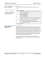
Basic I/O Operation
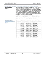
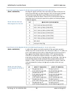
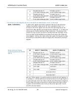
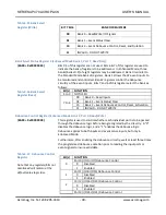
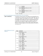
Note that the I/O lines of this module are assembled in groups of eight. Each
group of eight lines is referred to as a port. Ports 0-5 control and monitor
I/O lines 0-47. Additionally, ports are grouped eight to a bank. There are
four banks of ports used for controlling this module (Standard Mode, plus
Enhanced Mode Banks 0, 1, and 2), plus an additional register for enabling
the interrupt request and generating a software reset.
The input signals are inverted – when an output is ON (set to ‘1’), the
transistor sinks current and drives the output low (this is read back as a ‘1’).
Inputs include hysteresis. Further, each input port is connected such that the
current status of a given output port can be read back via the corresponding
input port. Individual ports may also be masked from writes to the port
when the port is intended for input only to help prevent contention errors.
Each port I/O line includes an integrated 4.7kΩ pull-up resistor to +5V. For
inputs, the pull-ups provide a low (false=0) input indication if the input is left
floating.
Each I/O line is in the form of an open-drain signal. Thus, any data written to
any port used as an input must be masked or always false (zero) to avoid
contention between the output circuitry and an input signal from an external
device. All 48 I/O lines are placed into the false (high output) state following
power-up or a system reset. The 4.7kΩ pull-up resistors installed on the
board provide digital high-drive capability for the output signals. If this does
not provide adequate current sourcing capability, another pullup can be
added external to the module.
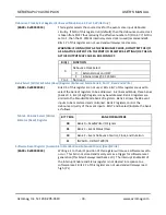
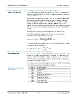
Enhanced Operating Mode
In the Enhanced Mode of operation, each port signal has an associated event
sense input and debounce logic circuit. The event sense inputs are used to
sense high-to-low level or low-to-high level transitions on digital input lines
at CMOS thresholds. Interrupts may also be triggered by events. The
optional debounce logic can act as a filter to “glitches” or transients present
on the received signals. Individual ports may be masked from writes to the
port when the port is used for input in order to prevent contention errors.
Further, event polarities may be defined as positive or negative for individual
nibbles (in groups of 4 I/O lines, or half ports). The Enhanced Mode is
entered by writing four unique bytes to the Port 7 register, in consecutive


