SERIES AP470 ACROPACK
USER
’S MANUAL
Acromag, Inc. Tel: 248-295-0310
- 40 -
http://www.acromag.com
- 40 -
www.acromag.com
6.
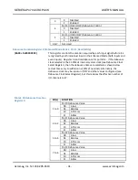
Write 40H to the port 7 address to select register bank 1 where the
event polarity requirements of our application will be configured. At
this point, you are in Enhanced Mode Bank 1 where access to the
event polarity/status registers is obtained.
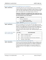
7.
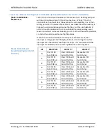
For change-of-state detection, both positive and negative polarities
must be sensed. As such, two channels are required to detect a
change-of-state on a single input signal. For our example, I/O00-
I/O03 will be used to detect positive events (low-to-high transitions);
I/O04-07 will be used to detect negative events (high-to-low
transitions). Write 01H to the port 6 address to set I/O00-I/O03 to
positive edge detection, and I/O04-07 to negative edge detection
(Port 4 and 5 I/O channels would use the Port 7 address). Note that
this port address has a dual function depending on whether a read
or write is being executed. As such, if the current polarity
configuration for the other ports must be preserved, then it must be
remembered since it cannot be read back.
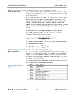
8.
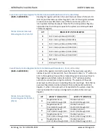
To enable event sensing for the port 0 I/O points, write FFH to the
Event Sense Status Register for port 0 I/O points at the port 0
address in this bank. Note that writing a 1 to a bit position enables
the event sense detector, while writing a 0 clears the event sensed
without enabling further event sensing.
9.
Write 00H to the port 7 address to select register bank 0 where the
port 0 input channels may be write-masked.
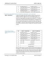
Note that the port 7 address bank selection only operates from bits
6 & 7 of this register, while bits 0-3 are used to select the event
polarity for port 4 & 5 I/O channels. Keep this in mind when
switching banks so as not to inadvertently change the polarity
configuration of port 4 & 5 input channels in the process of switching
register banks. Likewise, this register has a dual function depending
on whether a read or write is executed. As such, the polarity settings
cannot be read back and must be remembered if they are to be
preserved for successive writes.
At this point, you are in Enhanced Mode Bank 0 where access to the
write-mask register is obtained.
10.
For our example, port 0 I/O points are to be used for inputs only and
writes to this port should be masked to prevent the possibility of
data contention between the built-in output circuitry and the
devices driving these inputs. Write 01H to the port 7 address to mask
writes to port 0.
11.
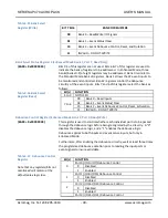
Read 01H from the port 7 address to verify bank 0 access (bits 6 & 7
are 0) and port 0 write masking (bit 0 is 1).


