SERIES AP220 / AP231 ACROPACK
USER
’S MANUAL
Acromag, Inc. Tel: 248-295-0310
- 22 -
http://www.acromag.com
- 22 -
https://www.acromag.com
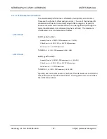
data written to the address specific channel’s input latch will continue to be
held until the Simultaneous Output Trigger register is written.
This will trigger the transfer of digital data from the D/A input latch to the
output latch and the digital to analog conversion producing the updated
analog output. The data written to this location is immaterial, since the
write is sufficient to complete the action.
RESET CONDITION: Defaults to Simultaneous Mode. All analog output
channels are set to "0 Volts".
Note:
The reset function resets only the DAC output latch of the input
double buffer. Therefore, after a reset, good data must be written to all the
input latches before enabling the Simultaneous Output Trigger for a DAC
output update. Otherwise, old or unknown data present in the input latches
will be transferred to the DAC output latch producing an undesired analog
output.
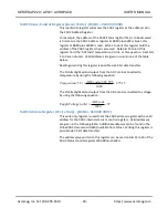
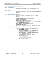
DAC Write Status Register (Read Only) - (BAR0 + 0x0000 0054)
This DAC Write Status register can be read to monitor the busy status after a
write to a DAC channel. New write of a DAC Channel register can be
performed no sooner than 1.6µs after the previous DAC write command is
executed.
The status of 16 DAC channels numbered 0 through 15 may be monitored
via this register. Data bits 0 to 15 reflect the status of DAC channels 0 to 15.
The channels corresponding status bit will be set low upon initiation of a
write operation and will remain low until the requested write operation has
completed. New write accesses to the DAC Channel register should not be
initiated unless its write busy status bit is set high.
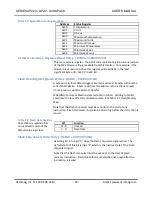
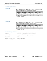
Control Register (Write Only) - (BAR0 + 0x0000 0058)
Asserting bit-
0 of this register to logic “1” returns the DACs to their default
power-on status where the output is clamped to ground and the output
buffer is powered down.
Asserting bit-
1 of this register to logic “1” sets the DAC register to zero
-scale,
midscale, or full-scale code (user selectable) and updates the DAC output.
Asserting bit-
7 of this register to logic “1” issues a software reset to the
module.
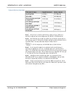
Bit-7 resets only the DAC output latch of the input double buffer. Therefore,
after a reset, good data must be written to all the input latches before
enabling the Transparent Mode or enabling the Simultaneous Output
Trigger for a DAC output update. Otherwise, old data or unknown data
present in the input latches will be transferred to the DAC output latch
producing an undesired analog output.


