SERIES IOS-320 I/O SERVER MODULE 12-BIT HIGH DENSITY ANALOG INPUT BOARD
__________________________________________________________________________________________
- 6 -
Acromag, Inc. Tel:248-295-0310 Fax:248-624-9234 Email:solutions@acromag.com http://www.acromag.com
3.0 PROGRAMMING INFORMATION
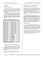
ID SPACE- (Read Only, 32 even-byte addresses)
Each IOS module contains an identification (ID) PROM that
resides in the ID space.. This area of memory contains 32 bytes
of information at most. Both fixed and variable information may
be present within the ID PROM. Fixed information includes the
"IOS" identifier, model number, and manufacturer's identification
codes. Variable information includes unique information required
for the module. The IOS-320 ID information does not contain any
variable (e.g. unique calibration) information. ID space bytes are
addressed using only the even addresses in a 64 byte block. The
IOS-320 ID space contents are shown in Table 3.1. Note that the
base-address for the IOS module ID space (see your carrier
board instructions) must be added to the addresses shown to
properly access ID space. Execution of an ID space read
requires 0 wait states.
Table 3.1: IOS-320 ID Space Identification (ID)
Hex Offset
From ID Base
Address
Numeric
Value
(Hex)
Field Description
00
49
02
50
04
41
06
43
08
A3
Acromag ID Code
0A
32
IOS Model Code
1
0C
00
Not Used (Revision)
0E
00
Reserved
10
00
Not Used
12
00
Not Used
14
0C
Total Number of ID
Bytes
16
2E
CRC
18 to 3E
00
Not Used
Notes (Table 3.2):
1. The IOS model number is represented by a two-digit code
within the ID space (the IOS-320 model is represented by 32
Hex).
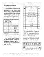
I/O SPACE ADDRESS MAP
This board is addressable in the I/O Server Module space to
control the acquisition of analog inputs from the field. The I/O
space may be as large as 64, 16-bit words (128 bytes), but the
IOS-320 only uses a portion of this space. The I/O space
address map for the IOS-320 is shown in Table 3.2. Note the
base address for the IOS module I/O space (see your carrier
board instructions) must be added to the addresses shown to
properly access the I/O space. All accesses are performed on a
16-bit word basis (D0..D15).
Table 3.2: IOS-320 I/O Space Address Memory Map
Base
Add+
(Hex)
High Byte
D15 D08
Low Byte
D07 D00
Base
Add+
(Hex)
01
R/W - Control Register
00
03
0F
Repeated Control Register
1
02
0E
11
W - ADC Convert Command
10
13
1F
Repeated ADC Convert Command
1
12
1E
21
R - Read ADC Data
20
23
2F
Repeated Read ADC Data
1
22
2E
31
3F
Not Used
2
30
3E
41
4F
Reserved
2
40
4E
51
7F
Not Used
2
50
7E
Notes (Table 3.1):
1. Registers appear in multiple locations in the memory map
because of simplified address decoding (these locations can
be ignored).
2. The IOS will respond to addresses that are “Not Used” with
an active IOS module acknowledge ACK*. The board will
return “0” for all address reads that are not used or reserved.
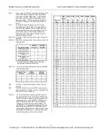
Control Register - (Read/Write, Base + 00H)
The IOS-320 Control Register reflects and controls analog
input channel data acquisition functions. This register must be
written/read, one word (D16) at a time. Execution of a Control
Register read (write) requires 0 (1) wait states. At reset all bits
are set to 0. The function of each bit is described as follows:
High Byte
MSB
D15
D14
D13
D12
D11
D10
D09
LSB
D08
CTRIG
Data
Ready
Not
used
Not
used
Not
used
Not
used
MODE
1
MODE
0
Low Byte
MSB
D07
D06
D05
D04
D03
D02
D01
LSB
D00
GSEL
1
GSEL
0
Not
used
SEL
HIGH
CH3
CH2
CH1
CH0

