EM11 User’s Manual
5. Description of Function Codes
101
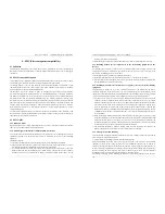
During the fixed length control, the length reset operation can be performed via the DI terminal. For details,
see the descriptions of b3-00 to b3-11.
Please set corresponding DI terminal with function 30 (Length count input) in applications. If the pulse
frequency is high, DI6 terminal must be used.
Code
Parameter Name
Setting Range
Default
C3-08
Set count value
1~65535
1000
C3-09
Designated count
value
1~65535 1000
The count value needs to be collected by DI terminal. Set the corresponding DI terminal with function
28(Counter input) in applications. If the pulse frequency is high, DI6 terminal must be used.
When the counting value reaches the set count value (C3-08), the DO terminal set with function (Set count
value reached) becomes ON. Then the counter stops counting.
When the counting value reaches the designated counting value (C3-09), the DO terminal set with function
(Designated count value reached) becomes ON. Then the counter continues to count until the set count
value is reached.
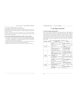
5.18 Group d0: Motor 1 Parameters
Code
Parameter Name
Setting Range
Default
d0-00
Rated motor power 0.1kw~1000.0 kW
Model
dependent
d0-01
Rated motor voltage 1V~2000 V
Model
dependent
d0-02
Rated motor current
0.01A~655.35 A (Frequency inverter power
≤
55 kW)
0.1A~6553.5 A (Frequency inverter power
≥
75 kW)
Model
dependent
d0-03
Rated motor
frequency
0.01 Hz~ maximum frequency
50.00Hz
d0-04
Rated motor
rotational speed
1rpm~65535rpm
Model
dependent
Set the parameters according to the motor nameplate no matter whether V/F control or vector control is
adopted.
To achieve better V/F or vector control performance, motor auto-tuning is required. The motor auto-tuning
accuracy depends on the correct setting of motor nameplate parameters.
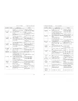
Code
Parameter Name
Setting Range
Default
d0-05
Stator resistance
(asynchronous motor)
0.001
Ω
~65.535
Ω
(frequency inverter power
≤
55 kW)
0.0001
Ω
~6.5535
Ω
(frequency inverter power
≥
75 kW)
Model
dependent
d0-06
Rotor resistance
(asynchronous motor)
0.001
Ω
~65.535
Ω
(Frequency inverter power
≤
55 kW)
0.0001
Ω
~6.5535
Ω
(frequency inverter power
≥
75 kW)
Model
dependent
d0-07
Leakage inductive
reactance
(asynchronous motor)
0.01mH~655.35 mH (frequency inverter power
≤
55 kW)
0.001mH~65.535 mH (frequency inverter power
≥
75
kW)
Model
dependent
d0-08
Mutual inductive
reactance
(asynchronous motor)
0.1mH~6553.5 mH (Frequency inverter power
≤
55 kW)
0.01mH~655.35 mH (Frequency inverter power
≥
75
kW)
Model
dependent
5. Description of Function Codes
EM11 User’s Manual
102
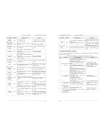
Code
Parameter Name
Setting Range
Default
d0-09
No-load current
(asynchronous motor)
0.01A ~ d0-02 (Frequency inverter power
≤
55 kW)
0.1A to d0-02 (Frequency inverter power
≥
75 kW)
Model
dependent
The parameters in d0-05 ~ d0-09 are asynchronous motor parameters. These parameters are unavailable on
the motor nameplate and are obtained by means of motor auto-tuning. Only d0-05 ~ d0-07 can be obtained
through static motor auto-tuning. Through complete motor auto-tuning, encoder phase sequence and
current loop PI can be obtained besides the parameters in d0-05 ~ d0-09.
When the "Rated motor power" (d0-00) or "Rated motor voltage" (d0-01) is changed; the frequency
inverter automatically restores values of d0-05 ~ d0-09, to restore setting of these 5 parameters according to
common standard Y series asynchronous motor.
If it is impossible to perform motor auto-tuning onsite, manually set the values of these parameters
according to data provided by the motor manufacturer.
Code
Parameter Name
Setting Range
Default
d0-15
Stator resistance
(synchronous motor)
0.001
Ω
~65.535
Ω
(frequency inverter power
≤
55 kW)
0.0001
Ω
~ 6.5535
Ω
(frequency inverter power
≥
75
kW)
Model
dependent
d0-16
Shaft D inductance
(synchronous motor)
0.01 mH ~655.35 mH (frequency inverter power
≤
55
kW)
0.001~65.535 mH (Frequency inverter power
≥
75 kW)
Model
dependent
d0-17
Shaft Q inductance
(synchronous motor)
0.01 mH ~655.35 mH (frequency inverter power
≤
55
kW)
0.001 mH~65.535 mH (frequency inverter power
≥
75
kW)
Model
dependent
d0-18
Back EMF
(synchronous motor)
0.1V~6553.5 V
Model
dependent
The d0-15~d0-18 are synchronous motor parameters. These parameters are unavailable on the nameplate of
most synchronous motors and can be obtained by means of "Synchronous motor no-load auto-tuning".
Through "Synchronous motor with-load auto-tuning", only the encoder phase sequence and installation
angle can be obtained.
Each time "Rated motor power" (d0-00) or "Rated motor voltage" (d0-01) is changed; the frequency
inverter will automatically modify the values of d0-15~ d0-18.
You can also directly set the parameters based on the data provided by the synchronous motor
manufacturer.
Code
Parameter Name
Setting Range
Default
d0-19
Encoder pulses per
revolution
1~32767 1024
This parameter is used to set the pulses per revolution (PPR) of ABZ or UVW incremental encoder. In VC
mode, the motor cannot run properly if this parameter is set incorrectly.


