GSK980MDc Milling CNC System User Manual
452
Appendix
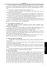
MANUAL mode. During the process the debugging tools should be collocated, because the positions
are needed to be relatively exact to avoid possible tool hitting in the next step tool changing.
Manipulato
r
boosting and retreating
The spindle needs to accomplish the orientation and return to the 2nd reference point, as well as
#1100=1 when the tool magazine is boosting or retreating. In debugging, no need to orient or
return to the reference point, please set K11.2 to 0. After debugging, set it to 1, to improve the
safety of the tool magazine.
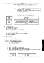
M65: the manipulator catches tools boosting to the right (in catching, make sure where to catch the
tool and make the spindle orientate to avoid manipulator hitting the machine)
M66: the manipulator retreats to the left (in retreating, make sure the tool clamped to avoid that the tool
falls from it)
If the function is not worked out:
1: parameter K11.2=1, make sure the spindle orientation accomplished and has returned to the
reference point. If both are done, please #1100=1, in mode of MDI or AUTO. If the function does not
worked out, please make sure Y1.4 (manipulator boosting) or Y1.5 (manipulator retreating) is 1 in
Ladder->PLC. If it is 1, please check the machine tools electric;
3: if there is a manipulator operation key, the above actins can be achieved in non-auto mode.
Overall debugging
Only every step above has been finished correctly that can the overall program debugging of
tool change be taking in MDI or AUTO mode.
Program:
Main program:
O0001 (O0001) // Tool change main program
T01
M6
//
call
subroutine
by M instructions other than M98.
T05 M6
M30
Tool change subroutine:
O9000 (O9000)
N1
#501=#4003
//save
G9091
N2 IF [#1000EQ1] GOTO 17
//if the target tool of the tool change is the current one, then skip
to the next
N3 G91 G30 Z0
//back to the 2nd reference point
N4
M19
//spindle
orientation
accomplished
N5 #1100=1
// back to the reference point and spindle orientation accomplished
N6 M65
//toolpot boosting to the right
N7
M54
//tool
releasing
N8 G30 Z0 P3
// back to the 3rd reference point
N9 #1100=0
//away from the 2nd reference point
N10
M60
//star
toolpot
rotation
N11 G30 Z0 P2
// back to the 2nd reference point
N12
M55
//tool
clamping
N13
#1100=1
//notify
to back to the 2nd reference point
N14 M66
// toolpot boosting to the left
Summary of Contents for 980MDc
Page 19: ...GSK980MDc Milling CNC User Manual XVIII ...
Page 20: ...1 I Programming Programming Ⅰ ...
Page 21: ...GSK980MDc Milling CNC System User Manual 2 I Programming ...
Page 139: ...GSK980MDc Milling CNC System User Manual 120 I Programming ...
Page 191: ...GSK980MDc Milling CNC System User Manual 172 I Programming ...
Page 192: ...173 Ⅱ Operation Ⅱ Operation ...
Page 193: ...GSK980MDc Milling CNC System User Manual 174 Ⅱ Operation ...
Page 200: ...Chapter 1 Operation Mode and Display 181 Ⅱ Operation ...
Page 201: ...GSK980MDc Milling CNC System User Manual 182 Ⅱ Operation ...
Page 249: ...GSK980MDc Milling CNC System User Manual 230 Ⅱ Operation ...
Page 253: ...GSK980MDc Milling CNC System User Manual 234 Ⅱ Operation ...
Page 259: ...GSK980MDc Milling CNC System User Manual 240 Ⅱ Operation ...
Page 265: ...GSK980MDc Milling CNC System User Manual 246 Ⅱ Operation ...
Page 293: ...GSK980MDc Milling CNC System User Manual 274 Ⅱ Operation ...
Page 295: ...GSK980MDc Milling CNC System User Manual 276 Ⅱ Operation ...
Page 319: ...GSK980MDc Milling CNC System User Manual 300 Ⅱ Operation ...
Page 320: ...301 Ⅲ Installation Ⅲ Installation ...
Page 321: ...GSK980MDc Milling CNC System User Manual 302 Ⅲ Installation ...
Page 345: ...GSK980MDc Milling CNC System User Manual 326 Ⅲ Installation ...
Page 391: ...GSK980MDc Milling CNC System User Manual 372 Ⅲ Installation ...
Page 392: ...Appendix 373 Appendix Appendix ...
Page 393: ...GSK980MDc Milling CNC System User Manual 374 Appendix ...
Page 394: ...Appendix 375 Appendix Appendix 1 Outline Dimension of GSK980MDc L N ...

