78
5 Programming: Tools
5.3 Tool Compensation
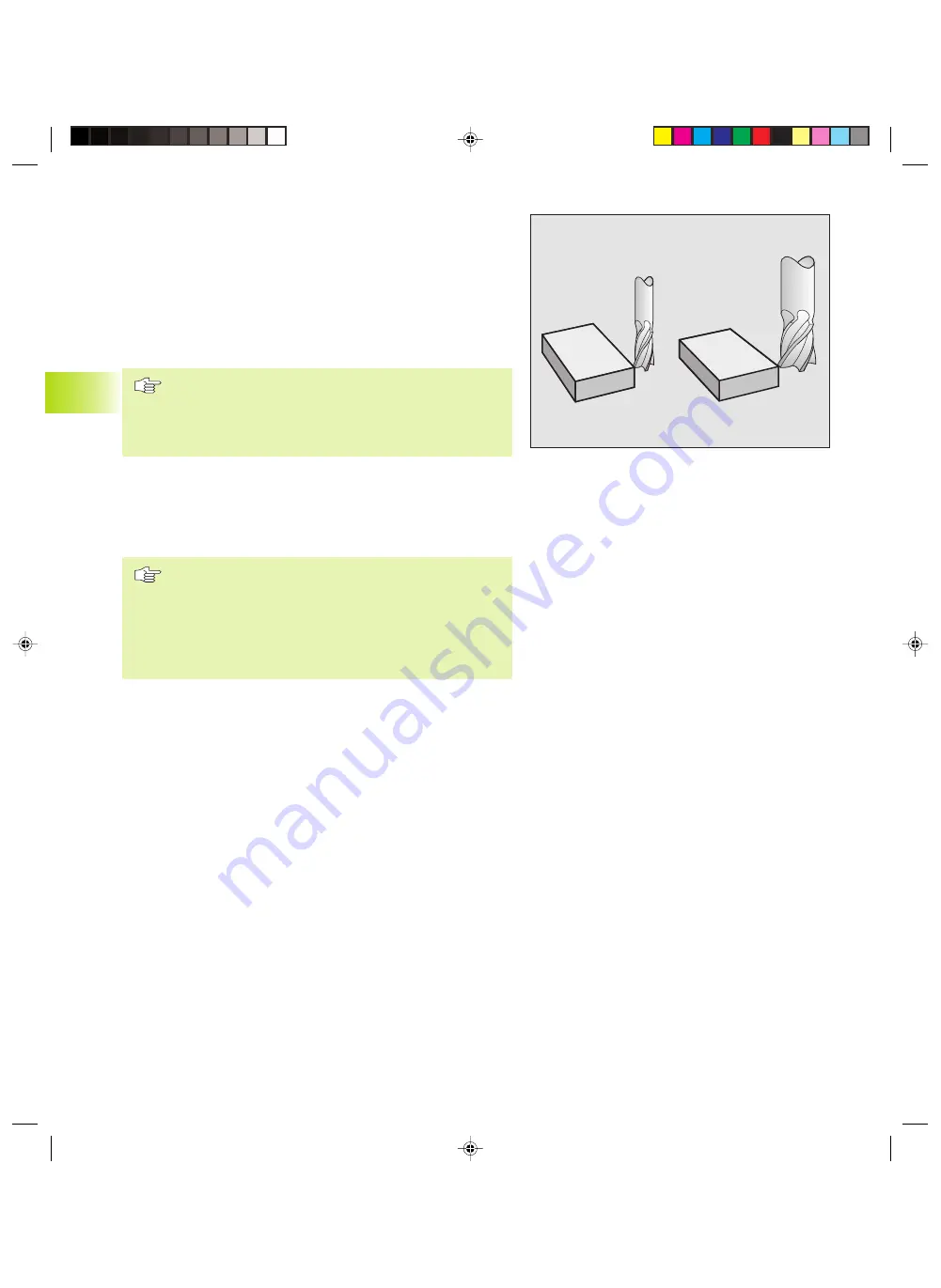
The TNC adjusts the spindle path in the tool axis by the
compensation value for the tool length. In the working plane, it
compensates the tool radius.
If you are writing the part program directly on the TNC, the tool
radius compensation is effective only in the working plane. The TNC
accounts for the compensation value in up to five axes including
the rotary axes.
If a part program generated by a CAD system contains
surface-normal vectors, the TNC can perform three-
dimensional tool compensation. For more information,
refer to section 5.4 “Three-Dimensional Tool
Compensation.”
Tool length compensation
Length compensation becomes effective automatically as soon as a
tool is called and the tool axis moves. To cancel length
compensation call a tool with the length L=0.
If you cancel a positive length compensation with TOOL
CALL 0, the distance between tool and workpiece will
be reduced.
After TOOL CALL, the path of the tool in the tool axis, as
entered in the part program, is adjusted by the difference
between the length of the previous tool and that of the
new one.
For tool length compensation, the TNC takes the delta values from
both the TOOL CALL block and the tool table into account:
Compensation value = L + DL
TOOL CALL
+ DL
TAB
, where
L
is the tool length L from the TOOL DEF block or
tool table
DL
TOOL CALL
is the oversize for length DL in the TOOL CALL block
(not taken into account by the position display)
DL
TAB
is the oversize for length DL in the tool table
5.3 T
ool Compensation
Fkap5.pm6
30.06.2006, 07:03
78
www.EngineeringBooksPdf.com
Summary of Contents for TNC 426 B
Page 3: ...BAUSKLA PM6 30 06 2006 07 03 2 www EngineeringBooksPdf com ...
Page 4: ...BAUSKLA PM6 30 06 2006 07 03 3 www EngineeringBooksPdf com ...
Page 6: ...CINHALT PM6 30 06 2006 07 03 2 www EngineeringBooksPdf com ...
Page 16: ...CINHALT PM6 30 06 2006 07 03 12 www EngineeringBooksPdf com ...
Page 17: ...Introduction 1 Dkap1 pm6 30 06 2006 07 03 1 www EngineeringBooksPdf com ...
Page 29: ...Manual Operation and Setup 2 Dkap2_3 pm6 30 06 2006 07 03 13 www EngineeringBooksPdf com ...
Page 83: ...Programming Tools 5 Fkap5 pm6 30 06 2006 07 03 67 www EngineeringBooksPdf com ...
Page 106: ...Fkap5 pm6 30 06 2006 07 03 90 www EngineeringBooksPdf com ...
Page 107: ...Programming Programming Contours 6 Gkap6 pm6 30 06 2006 07 04 91 www EngineeringBooksPdf com ...
Page 165: ...Hkap7 pm6 30 06 2006 07 03 150 www EngineeringBooksPdf com ...
Page 166: ...Programming Cycles 8 kkap8 pm6 30 06 2006 07 03 151 www EngineeringBooksPdf com ...
Page 253: ...kkap8 pm6 30 06 2006 07 04 238 www EngineeringBooksPdf com ...
Page 265: ...LKAP9 PM6 30 06 2006 07 04 250 www EngineeringBooksPdf com ...
Page 266: ...Programming Q Parameters 10 MKAP10 PM6 30 06 2006 07 04 251 www EngineeringBooksPdf com ...
Page 297: ...MKAP10 PM6 30 06 2006 07 04 282 www EngineeringBooksPdf com ...
Page 298: ...Test Run and Program Run 11 NKAP11 PM6 30 06 2006 07 04 283 www EngineeringBooksPdf com ...
Page 312: ...MOD Functions 12 Okap12 pm6 30 06 2006 07 04 297 www EngineeringBooksPdf com ...
Page 332: ...Tables and Overviews 13 Pkap13 pm6 30 06 2006 07 04 317 www EngineeringBooksPdf com ...


