Chapter 3 Programming
3
– 56
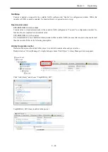
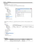
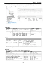
Configuration
Parameter
Descriptions
Choices
Default
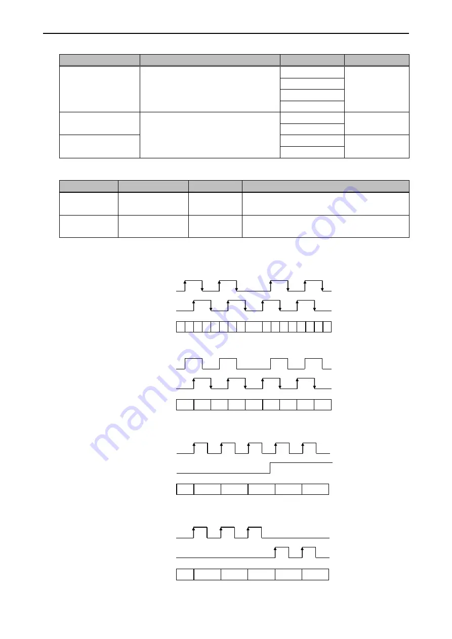
Counter mode
4 different counter modes are supported as
shown below.
2-phase 4-edge
2-phase 4-edge
2-phase
Pulse + Direction
CW/CCW
Marker (Z) input
When Marker (Z) input is enabled and
rising/falling edge of the input is detected,
the counter value is reset (0).
Disable
Disable
Enable
Marker (Z) input type
Rising edge
Rising edge
Falling edge
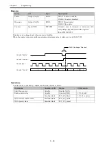
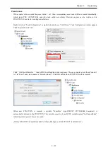
Mapping
Name
I/O
Type
Descriptions
Enable
Output (%QX)
BOOL
TRUE: Counter is enabled.
FALSE: Counter is disabled.
Counter
Input (%ID)
DWORD
Counted value is stored in this register.
0 to 4,294,967,295
When the counter value exceeds the maximum or minimum value, it returns to 0 or 4,294,967,295.
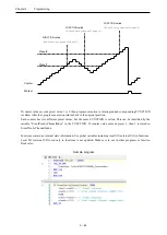
Counter mode
1 2 3 4 5 6 7
8
7 6 5 4 3 2
0
1 0
Counter
value
Phase A
Phase B
2-Phase 4-edge
2-Phase
0
Counter
value
Phase A
Phase B
2
1
3
4
2
3
1
0
Pulse + Direction
CW/CCW
0
Counter
value
1
2
3
2
1
Phase A
Phase B
0
Counter
value
Phase A
Phase B
1
2
3
2
1
Summary of Contents for EH-A14EDR
Page 6: ...MEMO ...
Page 10: ...MEMO ...
Page 141: ...Chapter 3 Programming 3 81 Program ...
Page 166: ...Chapter 5 Maintenance 5 4 MEMO ...
Page 170: ...Appendix A1 4 MEMO ...

