The purpose of link-layer packets is to provide a mechanism for getting command packets into a par-
ticular SKB device. Standard command packets are placed in the data payload section of the link-
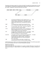
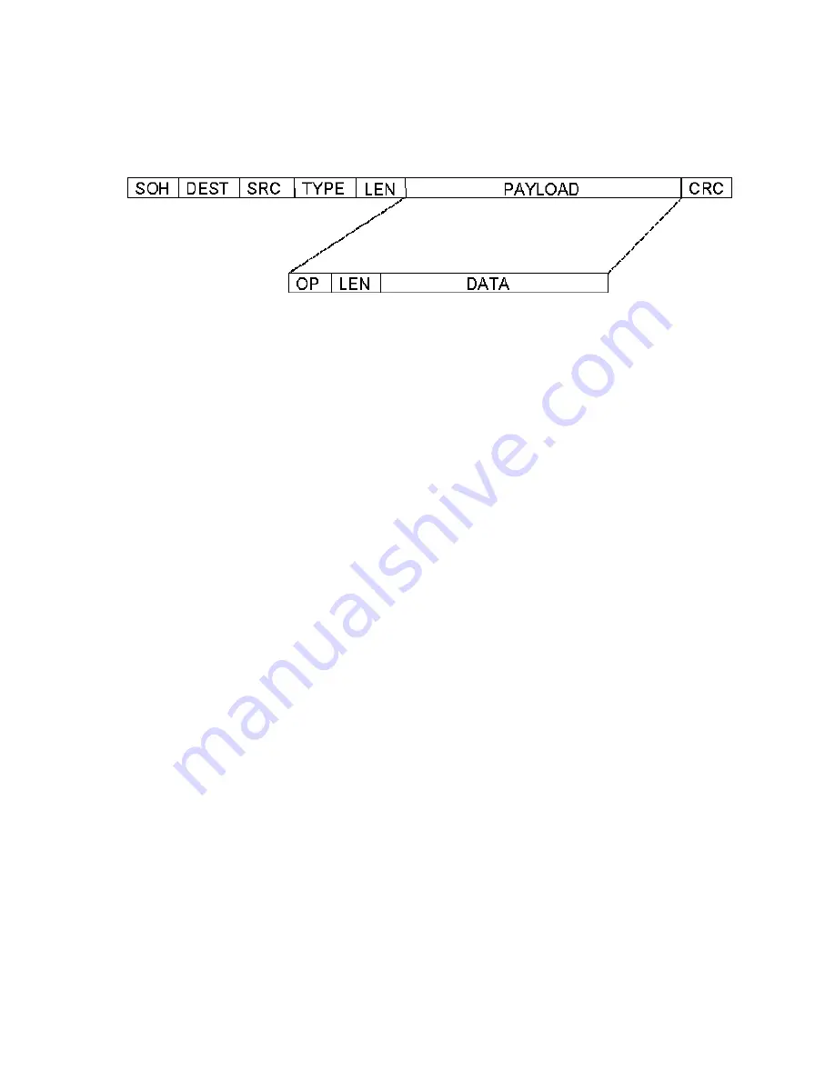
layer packet. Graphically, the RS-485 link packet is as follows:
The RS-485 protocol is based on a command-acknowledge architecture: For each link-layer packet
sent, an acknowledgement (in the form of and ACK packet) is provided.
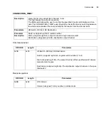
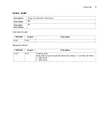
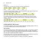
RS485 Packet Example
Assume that a device with network address of 1 is present on the RS-485 network. The master will
connect input channel 1 to output channel 2 on the first logical switch by sending the following com-
mand:
SOH
The START-OF-HEADER byte, always defined as 0x81. If a
LEN, PAYLOAD, or CRC byte is has a value of 0x81, the byte
should be actually transmitted twice. This indicates that the
bytes should be interpreted as a valid packet byte rather than
a SOH.
1 byte
DEST
The destination device address where the packet is being
sent. All other devices will ignore the rest of the packet bytes.
1 byte
SRC
The device address of the sender. This byte is remembered
and used to send ACK or response packets.
1 byte
TYPE
Defines the purpose of the packet: a value of 0 means this is a
packet containing data, and a value of 1 means this packet is
an ACKnowledgement to a previous data packet.
1 byte
LEN
The total number of payload data bytes (8-bits) . This number
does NOT include the CRC bytes, which are concatenated to
the end of the packet prior to actually transmitting.
2 bytes
PAYLOAD
These bytes represent the non-RS-485-specific data portion of
the link-layer packet. Typically, a complete command (or
response) packet is included in this field. The RS-485 sub-
system will pass this payload up to the session/application
layer of the software.
< 256 bytes
CRC
The cyclical redundancy check (CRC) is calculated on the
assembled link-layer packet (including any/all byte swapping).
2 bytes
Summary of Contents for SKB Series
Page 1: ...SKB SERIES FIBEROPTIC SWITCH MODULE User Manual ...
Page 2: ...ii 10109002 Rev 001 August 2001 2001 JDS Uniphase All rights reserved ...
Page 4: ...iv ...
Page 11: ...7 Contents ...
Page 13: ...9 List of Figures ...
Page 15: ...11 List of Tables ...
Page 19: ...4 Safety Information Instructions and Symbols ...
Page 25: ...10 Introduction ...
Page 53: ...38 Operation and Control Instructions ...
Page 91: ...76 Commands ...
Page 111: ...96 Application Notes ...
Page 113: ...98 Service ...

