LinMot Linear-Rotary Motors
The ratio can be freely defined. Keep in mind that the "position" parameter type is defined as a 32-bit value and the
maximum position resolution is 0.1 µm. This means that the maximum stroke is limited to between -214748 mm
and 214748 mm.
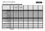
Position [mm]
-214748 to 214748
1 revolution = 36 mm (1° == 0.1 mm)
Maximum number of revolutions = 11930
1 revolution = 360 mm (1° == 1 mm)
Maximum number of revolutions = 1193
The ratio, however, affects not only the positions but also the PID controller. The table below shows an example of
this:
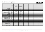
P [A/mm]
5
1 revolution = 36 mm (1° == 0.1 mm)
For a deviation of 1°, the drive reacts with 0.5 A
1 revolution = 360 mm (1° == 1 mm)
For a deviation of 1°, the drive reacts with 5 A
This means that if the "Motor Angle to Position Ratio" is changed, the controller parameters must be
(manually) adjusted as well.
Example of motion using a VAI motion command
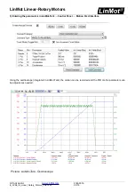
A VAI Motion Command (motion using the Velocity Acceleration Interpolator) can be started directly via the LinMot
Talk program.
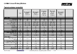
1) Definition of the movement:
Number of revolutions
25
Acceleration phase
100 [ms]
Maximal velocity
1500 [rpm]
Delay
50 [ms]
1 Revolution
36 [mm]
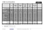
2) Converting the rotary parameters into the linear system:
Target Position
[
mm
]=
Number of revolutions
∗
36
[
mm
]=
900
[
mm
]
Maximal Velocity
[
m
/
s
]=(
1500
[
1
/
min
]∗
0.036
[
m
])/
60
=
0.9
[
m
/
s
]
Acceleration
[
m
/
s
2
]=
Maximal Velocity
[
m
/
s
]/
0.1
[
s
]=
9
[
m
/
s
2
]
Deceleration
[
m
/
s
2
]=
Maximal Velocity
[
m
/
s
]/
0.05
[
s
]=
18
[
m
/
s
2
]
NTI AG/ LinMot
0185-0015-
E_2V94_IG_Linear_Rotary_Motors_PR01.odt
21/79

