Color Monitor Networking________________________________________________________
Ctrl Nr: PM375103 Revision: 003
15
2.6
Modbus Addressing
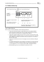
Refer to Figure 10
, “Modbus Addressing,” with the following bullet points:
•
The Monitor is a Modbus master to its downstream devices. The upstream Modbus
master cannot directly address these devices, but rather addresses them through the
Monitor. Upstream and downstream are separate Modbus segments.
•
The Monitor’s upstream address can be set to from 1 to 255, but you must leave enough
addressing capacity for downstream devices. The monitor will not respond to a command
sent to address 0. The address is set in Monitor Setup. See Section 3
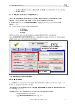
.2.3 “TCP/IP and
Modbus TCP/IP Setup.”
•
The
Monitor’s downstream devices must be assigned consecutive addresses starting at
address 1.
•
For upstream addressing these device addresses are remapped as successor addresses
to the Monitor. If the Monitor has upstream address 30, the downstream addresses 1, 2,
3, 4 are remapped to 31, 32, 33, 34 as seen from the BMS or other Modbus Master.
•
Modbus addressing is the same for Modbus RTU and Modbus TCP/IP.
1 2 3 4
Downstream Modbus addresses must be
assigned sequentially from 1.
31 32 33 34
Downstream Modbus addresses are adjusted by
the Monitor’s upstream address.
BCMS
BCMS
PB1 PB2 PB3 PB4
RPP
Figure 10 Modbus Addressing
30
30
30 = Monitor’s assigned upstream
address.
These addresses are visible from
the upstream Modbus master:
To upstream
Modbus
master (BMS,
DCIM, etc.)
Monitor’s Upstream Modbus Segment
Monitor’s Downstream Modbus Segment


