5756B
53
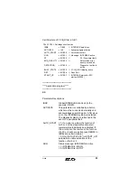
Call Structure of FC IB_DIAG in OB 1:
************************************
**** Application program ****
************************************
BE
Parameter Descriptions:
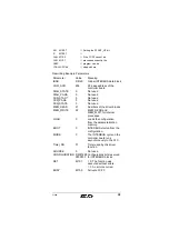
CALL FC24 // Call diagnostic function
IBDB
:= DB20
// INTERBUS data block
ACTIVATE
:= I4.0
// Acknowledgment button
AUTO_START := M100.0
// Automatic restart
RUN
:= M100.1
// Message: INTERBUS active
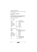
PF
:= M100.2
//
PF (Peripheral fault)
BUS_QUALITY := M100.3
//
Determined error
density exceeded
DETECTION
:= M100.4
//
Diagnostic routine is
active
BUSY_STATE
:= M100.5
// FC IB_DIAG display active
RET
:= M100.6
// Result bit
START_UP
:= M100.7
// INTERBUS start after PLC
startup (OB100)
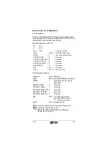
IBDB
Global INTERBUS data block (in the
example: DB 20).
ACTIVATE
This parameter is controlled by a button
which must be connected externally and
acknowledges an existing error. After a bus
error, the INTERBUS system is restarted.
The diagnostic display is refreshed in the
event of a peripheral fault.
AUTO_START
= 1: If an error occurred, the function of
bit 0 or 2 of the standard function start
register will automatically be activated. If
the error cannot be removed, the function
of bit 0 or 2 will be re-called (see DBW98 in
IBDB) at a certain interval.
= 0: Only the "ACTIVATE" (or START_UP)
parameters enable activation of the
function of bit 0 or 2.
RUN
Status message: INTERBUS is active.
= 1: INTERBUS is in RUN
= 0: INTERBUS is in STOP

