34
Rockwell Automation Publication 1794-UM061B-EN-P - March 2020
Chapter 3
About the FLEX I/O Diagnostic Output Module
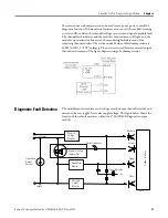
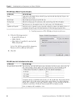
• Channel I/O Status- This indicator displays the on/off state of each
output channel, and channel wiring fault conditions:
–
Off indicates that the output channel is off with no faults.
–
Yellow indicates that the output channel is on with no faults.
–
Red indicates either an output channel open or short condition.
• Module Fault Status- This indictor turns red for individual output channel
opens, shorts, or module reverse power conditions.
With no fault, the module fault indicator turns off.
Module Limitations
Unused Output Channels
You must connect dummy resistors to unused output channels to mask the
diagnostic function. If these external resistors are not used, the module’s sensing
circuitry will not detect the intended voltage or current and signal a module fault.
The channel fault indicator and the module’s fault indicator will light. The
module’s open and error bits are set, thus rendering fault detection of the
remaining channels useless. The recommended value of this dummy resistor is
10 k
(+10%), 1/8 W (or larger). The resistor is wired between unused output
channels and common.
Configure Your Output
Diagnostic Module
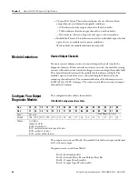
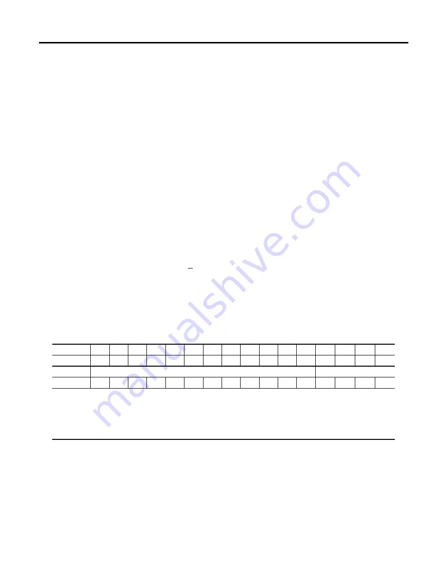
The configuration data table is shown below.
1794-OB16D Configuration Data Table
The outputs are written in Word 2. Decimal bit 00 is the first output and decimal
bit 15 is the last output.
Diagnostic status is read from Word 1:
Bit 00: Module Error Bit
Bit 01: External Power Reverse Polarity Error Bit
Bit 02: Output Short Error Bit
Bit 03: Output Open Wire Error Bit
Dec.
15
14
13
12
11
10
09
08
07
06
05
04
03
02
01
00
Oct.
17
16
15
14
13
12
11
10
07
06
05
04
03
02
01
00
Read 1
Not used
Read Diagnostics Status
Write 2
O15
O14
O13
O12
O11
O10
O9
O8
O7
O6
O5
O4
O3
02
O1
O0
Where
O = Output
Diagnostic status;
Bit 00 = module error;
Bit 01 = external power reverse polarity error;
Bit 02 = output short error;
Bit 03 = output open wire error

