User Manual
User Manual
79
78
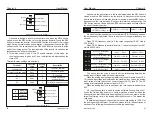
CRC will write 0xFFFF in superior host, and call a program to process
the consecutive 8 bytes in the message as well as the values in the register.
Only 8-bit data of each character is valid to CRC, the others are all invalid,
including start bit, stop bit and parity check bit.
During the operation of CRC, each of 8-bit character is exclusive(XOR)
with register content separately; result will be inclined to the least significant
bit(LSB) while the most significant bit will be filled with Zero. LSB will be
extracted from the data for checking; if LSB is one, register will be
exclusive(XOR) with preset value separately; if LSB is zero, calculation will
not be conducted. This instruction of process will repeat for 8 times; when it
comes to the last bit (8th bit), the next 8-bit bytes will be exclusive(XOR) with
register value again. The final value in the register is the CRC value after the
calculations of all the bytes in the message.
When CRC is added into the message, lower byte will be added first,
then the high byte. The simple function of CRC is as follows:
unsigned int crc_chk_value
(
unsigned char *data_value,unsigned char length
)
{
unsigned int crc_value=0xFFFF;
int i;
{
return
(
crc_value
)
;
else
}
while
(
length--
)
{
}
crc_value=
(
crc_value>>1
)
}
}
}
crc_value=
(
crc_value>>1
)
if
(
crc_value&0x0001
)
^0xa001
for
(
i=0;i<8;i++
)
{
{
crc_value^=*dat+;
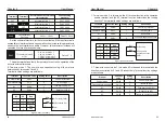
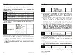
1. Descriptions of the other functions' address
Parameters address monitoring:
Control command
(valid when P0-02 is changed into 3)
Status of Converter
9.5 Read-write rules of parameter address for function code
Register
address
Address
S/N
Data Description
0xDC
Setting freqency
0xDD
221
Output freqency
0xDE
222
Output Current
0xDF
223
Busbar voltage
0xE0
224
Motor speed
0xE1
225
Percentage of current
0xE2
226
IGBT temperature
0xE3
227
Output voltage
0xE4
228
Output power
0xE5
229
Count value
Register
address
Address
S/N
0xE6
230
PI preset value
0xE7
231
PI feedback value
0xE8
232
Run time
0xE9
233
Input interface
0xEA
234
Output interface
0xEB
235
Rated power
0xEC
236
Compensation
Frequency
0xED
237
Compensation voltage
0xEE
238
Phase angle
0xEF
239
Load factors
Register
address
Address
S/N
0xC8
201
1 : FWD run
Data Description
Data Description
2 : FWD jogging
5 : REV run
6 : REV jogging
8 : Stop
16 : Regular stopping
32 : Reset
Register
address
Address
S/N
0xF0
241
0 : Operating
Data Description
1 : FWD running
2 : REV running
6 : Malfunctioning
0xF2
240
0xF3
242
Analog AI2
given value
0xF4
244
Keyboard
potentiometer set
value
245
Analog AI1
given value
Vector control
slip gain
50%
〜
200%
Default
:
100%
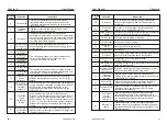
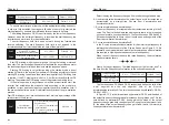
P2-06
For speed sensor vector control, this parameter can adjust the output
current of the inverter under the same load.
For speed sensorless vector control, this parameter is increased when the
speed is lower when the motor is loaded, and vice versa.
For speed sensor vector control, this parameter can adjust the output
current of the inverter under the same load.
Time constant of
speed loop filter
0.000s
〜
0.100s
Default
:
0.050s
P2-07
In vector control mode, the output of the speed loop regulator is the torque
current command, which is used to filter the torque command. This parameter
generally does not need to be adjusted. When the speed fluctuates greatly,
the filtering time can be appropriately increased. If the motor oscillates, the
parameter should be appropriately reduced. The speed loop filter time
constant is small, the inverter output torque may fluctuate greatly, but the
speed response is fast.
Vector controlled
over-excitation gain
0
〜
200
Default
:
64
P2-08
During deceleration, the over-excitation control can suppress the rise of
the bus voltage and avoid overvoltage faults. The larger the over-excitation
gain, the stronger the suppression effect.
In the case where the inverter is easy to overvoltage alarm during the
deceleration process, it is necessary to increase the over-excitation gain.
However, the over-excitation gain is too large, which tends to cause an
increase in the output current, which needs to be weighed in the application.
For applications where the inertia is small, there is no voltage rise during
motor deceleration. It is recommended to set the over-excitation gain to 0. For
those with braking resistors, it is also recommended to set the over-excitation
gain to 0.
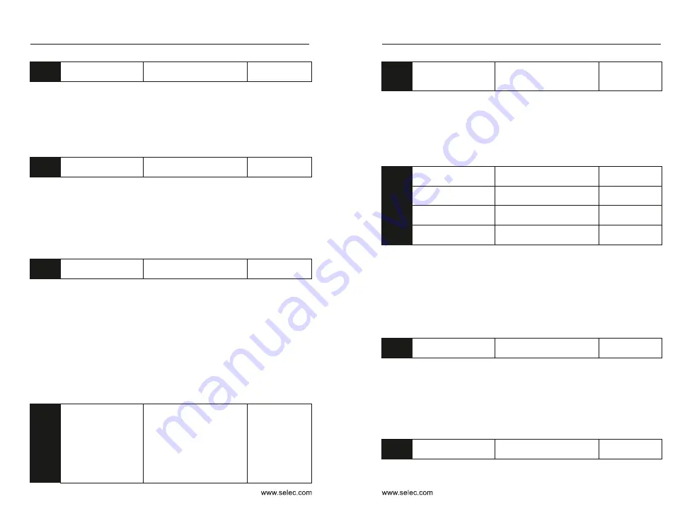
Torque upper limit
source in speed
control mode
0
:
Function code P2-10
setting
1: AI1 2: AI2 3: AI3
4: Pulse setting
5: Communication setting
6: MIN (AI1, AI2)
7: MAX (AI1, AI2) The full
scale of the 1-7 option
corresponds to P2-10
Default
:
0
Digital setting of
torque upper limit
in speed control mode
0.0%
〜
200.0%
Default
:
150.0%
P2-09
P2-10
In the speed control mode, the maximum value of the inverter output
torque is controlled by the torque upper limit source.
P2-09 is used to select the setting source of the upper torque limit. When
it is set by analog quantity, pulse and communication, the corresponding
setting of 100% corresponds to P2-10, and 100% of P2-10 is the rated torque
of the inverter.
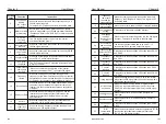
Excitation adjustment
proportional gain
0
〜
60000
Default
:
2000
Excitation regulation
integral gain
0
〜
60000
Default
:
1300
Torque adjustment
proportional gain
0
〜
60000
Default
:
2000
Torque adjustment
integral gain
0
〜
60000
Default
:
1300
P2-13
P2-14
P2-15
P2-16
The vector control current loop PI adjusts the parameter, which is
automatically obtained after the asynchronous machine is fully tuned, and
generally does not need to be modified.
Need to be reminded that the integral regulator of the current loop does
not use the integration time as the dimension, but directly sets the integral
gain. The current loop PI gain setting is too large, which may cause the entire
control loop to oscillate, so when the current oscillation or torque fluctuation
is large, the PI proportional gain or integral gain can be manually reduced.
Maximum output
voltage coefficient
100%~110%
Default
:
105%
P2-20
The maximum output voltage coefficient indicates the boosting capacity
of the maximum output voltage of the inverter. Increasing the F2-20 can
increase the maximum load capacity of the weak field of the motor, but the
increase of the motor current ripple will increase the heat generated by the
motor; otherwise, the maximum band of the weak field of the motor The load
capacity will decrease, but the motor current ripple will decrease, which will
reduce the heat generated by the motor. Generally no adjustment required.
Weak magnetic zone
maximum torque factor
50%~200%
Default
:
100%
P2-21
Chapter 6
Chapter 6


