116
M3i.48xx / M3i.48xx-exp Manual
General information
ABA mode (dual timebase)
ABA mode (dual timebase)
General information
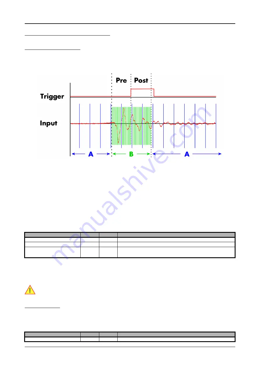
The ABA mode allows the acquisition of data with a dual timebase. In case of trigger event the inputs are sampled very fast with the pro-
grammed sampling rate. This part is similar to the Multiple Recording option. But instead of having no data in between the segments one has
the opportunity to continuously sample the inputs with a slower sampling rate the whole time. Combining this with the recording of the
timestamps gives you a complete acquisition with a dual timebase as shown in the drawing.
As seen in the drawing the area around the trigger event is sampled between pretrigger and posttrigger with full sampling speed (area B of
the acquisition). Outside of this area B the input is sampled with the slower ABA clock (area A of the acquisition). As changing sampling
clock on the fly is not possible there is no real change in the sampling speed but area A runs continuously with a slow sampling speed without
stopping when the fast sampling takes place. As a result one gets a continuous slow sampled acquisition (area A) with some fast sampled
parts (area B)
The ABA mode is available for standard recording as well as for FIFO recording. In case of FIFO recording ABA and the acquisition of the
fast sampled segments will run continuously until it is stopped by the user.
A second possible application for the ABA mode is the use of the ABA data for slow monitoring of the inputs while waiting for an acquisition.
In that case one wouldn’t record the timestamps but simply monitor the current values by acquiring ABA data.
The ABA mode needs a second clock base. As explained above the acquisition is not changing the sampling clock but runs the slower ac-
quisition with a divided clock. The ABA memory setup including the divider value can be programmed with the following registers
The resulting ABA clock is then calculated by sampling rate / ABA divider.
Each segment can consist of pretrigger and/or posttrigger samples. The user always has to set the total segment size and the posttrigger,
while the pretrigger is calculated within the driver with the formula: [pretrigger] = [segment size] - [posttrigger].
When using ABA mode or Multiple Recording the maximum pretrigger is limited depending on the number
of active channels. When the calculated value exceeds that limit, the driver will return the error
ERR_PRETRIGGERLEN.
Standard Mode
With every detected trigger event one data block is filled with data. The length of one ABA segment is set by the value of the segmentsize
register. The total amount of samples to be recorded is defined by the memsize register.
Memsize must be set to a a multiple of the segment size. The table below shows the register for enabling standard ABA mode. For detailed
information on how to setup and start the standard acquisition mode please refer to the according chapter earlier in this manual.
Register
Value
Direction
Description
SPC_SEGMENTSIZE
10010
read/write
Size of one Multiple Recording segment: the number of samples to be record after each trigger event.
SPC_POSTTRIGGER
10030
read/write
Defines the number of samples to be recorded after each trigger event.
SPC_ABADIVIDER
10040
read/write
Programs the divider which is used to sample slow ABA data:
For 12 bit and 14 bit cards : between 8 and 131064 in steps of 8
For 8 bit: between 16 and 262128 in steps of 16
Register
Value
Direction
Description
SPC_CARDMODE
9500
read/write
Defines the used operating mode


