98
M3i.48xx / M3i.48xx-exp Manual
Channel Trigger
Trigger modes and appendant registers
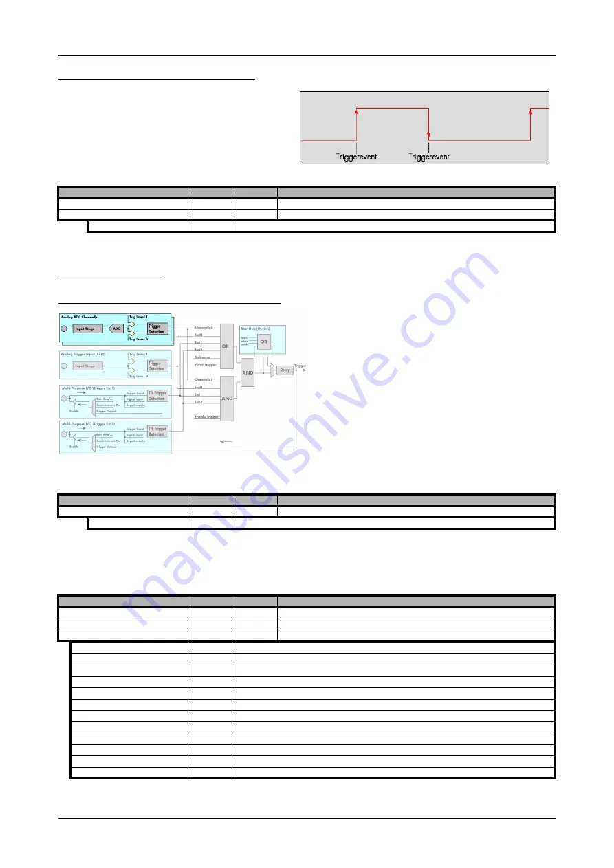
Positive and negative TTL trigger (both edges)
This mode is for detecting the rising and falling edges of an ex-
ternal TTL signal. The board will trigger on the first rising or falling
edge that is detected after starting the board. The next trigger-
event will then be detected, if the actual recording/replay has fin-
ished and the board is armed and waiting for a trigger again.
Channel Trigger
Overview of the channel trigger registers
The channel trigger modes are the most common modes, compared
to external equipment like oscilloscopes. The huge variety of different
channel trigger modes enable you to observe nearly any part of the
analog signal. This chapter is about to explain the different modes in
detail. To enable the channel trigger, you have to set the channel trig-
germode register accordingly. Therefore you have to choose, if you
either want only one channel to be the trigger source, or if you want
to combine two or more channels to a logical OR or a logical AND
trigger.
For all channel trigger modes, the OR mask must contain the corresponding input channels (channel 0 taken as example here):.
The following table shows the according registers for the two general channel trigger modes. It lists the maximum of the available channel
mode registers for your card’s series. So it can be that you have less channels installed on your specific card and therefore have less valid
channel mode registers. If you try to set a channel, that is not installed on your specific card, a error message will be returned.
Register
Value
Direction
Description
SPC_TRIG_EXT1_MODE
40511
read/write
Sets the trigger mode for multi purpose X0 trigger input.
SPC_TRIG_EXT2_MODE
40512
read/write
Sets the trigger mode for multi purpose X1 trigger input.
SPC_TM_BOTH
4h
Sets the trigger mode for external TTL trigger to detect positive and negative edges.
Register
Value
Direction
Description
SPC_TRIG_CH_ORMASK0
40460
read/write
Defines the OR mask for the channel trigger sources.
SPC_TMASK0_CH0
1h
Enables channel0 input for the channel OR mask
Register
Value
Direction
Description
SPC_TRIG_CH_AVAILMODES
40600
read
Bitmask, in which all bits of the below mentioned modes for the channel trigger are set, if available.
SPC_TRIG_CH0_MODE
40610
read/write
Sets the trigger mode for channel 0. Channel 0 must be enabled in the channel OR/AND mask.
SPC_TRIG_CH1_MODE
40611
read/write
Sets the trigger mode for channel 1. Channel 1 must be enabled in the channel OR/AND mask.
SPC_TM_NONE
00000000h
Channel is not used for trigger detection. This is as with the trigger masks another possibility for disabling channels.
SPC_TM_POS
00000001h
Enables the trigger detection for positive edges
SPC_TM_NEG
00000002h
Enables the trigger detection for negative edges
SPC_TM_BOTH
00000004h
Enables the trigger detection for positive and negative edges
SPC_TM_POS | SPC_TM_REARM
01000001h
Trigger detection for positive edges on lebel 0. Trigger is armed when crossing level 1 to avoid false trigger on noise
SPC_TM_NEG | SPC_TM_REARM
01000002h
Trigger detection for negative edges on lebel 1. Trigger is armed when crossing level 0 to avoid false trigger on noise
SPC_TM_LOW
00000010h
Enables the trigger detection for LOW levels
SPC_TM_HIGH
00000008h
Enables the trigger detection for HIGH levels
SPC_TM_WINENTER
00000020h
Enables the window trigger for entering signals
SPC_TM_WINLEAVE
00000040h
Enables the window trigger for leaving signals
SPC_TM_INWIN
00000080h
Enables the window trigger for inner signals
SPC_TM_OUTSIDEWIN
00000100h
Enables the window trigger for outer signals


