Acquisition modes
Buffer handling
(c) Spectrum GmbH
75
The given memory and memory / divider figures depend on the installed on-board memory as listed below:
Please keep in mind that this table shows all values at once. Only the absolute maximum and minimum values are shown. There might be
additional limitations. Which of these values is programmed depends on the used mode. Please read the detailed documentation of the mode.
Buffer handling
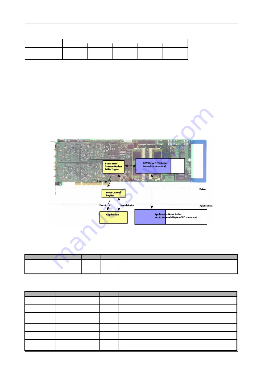
To handle the huge amount of data that can possibly be acquired with the M2i/M3i series cards, there is a very reliable two step buffer
strategy set up. The on-board memory of the card can be completely used as a real FIFO buffer. In addition a part of the PC memory can be
used as an additional software buffer. Transfer between hardware FIFO and software buffer is performed interrupt driven and automatically
by the driver to get best performance. The following drawing will give you an overview of the structure of the data transfer handling:
A data buffer handshake is implemented in the driver which allows to run the card in different data transfer modes. The software transfer
buffer is handled as one large buffer which is on the one side controlled by the driver and filled automatically by busmaster DMA from/to
the hardware FIFO buffer and on the other hand it is handled by the user who set’s parts of this software buffer available for the driver for
further transfer. The handshake is fulfilled with the following 3 software registers:
Internally the card handles two counters, a user counter and a card counter. Depending on the transfer direction the software registers have
slightly different meanings:
Installed Memory
128 MSample
256 MSample
512 MSample
1 GSample
2 GSample
Mem
128 MSample
256 MSample
512 MSample
1 GSample
2 GSample
Mem / 2
64 MSample
128 MSample
256 MSample
512 MSample
1 GSample
Mem / 4
32 MSample
64 MSample
128 MSample
256 MSample
512 MSample
Register
Value
Direction
Description
SPC_DATA_AVAIL_USER_LEN
200
read
Returns the number of currently to the user available bytes inside a sample data transfer.
SPC_DATA_AVAIL_USER_POS
201
read
Returns the position as byte index where the currently available data samples start.
SPC_DATA_AVAIL_CARD_LEN
202
write
Writes the number of bytes that the card can now use for sample data transfer again
Transfer direction
Register
Direction
Description
Write to card
SPC_DATA_AVAIL_USER_LEN
read
This register contains the currently available number of bytes that are free to write new data to the
card. The user can now fill this amount of bytes with new data to be transferred.
SPC_DATA_AVAIL_CARD_LEN
write
After filling an amount of the buffer with new data to transfer to card, the user tells the driver with this
register that the amount of data is now ready to transfer.
Read from card
SPC_DATA_AVAIL_USER_LEN
read
This register contains the currently available number of bytes that are filled with newly transferred
data. The user can now use this data for own purposes, copy it, write it to disk or start calculations
with this data.
SPC_DATA_AVAIL_CARD_LEN
write
After finishing the job with the new available data the user needs to tell the driver that this amount of
bytes is again free for new data to be transferred.
Any direction
SPC_DATA_AVAIL_USER_POS
read
The register holds the current byte index position where the available bytes start. The register is just
intended to help you and to avoid own position calculation
Any direction
SPC_FILLSIZEPROMILLE
read
The register holds the current fill size of the on-board memory (FIFO buffer) in promille (1/1000) of
the full on-board memory. Please note that the hardware reports the fill size only in 1/16 parts of the
full memory. The reported fill size is therefore only shown in 1000/16 = 63 promille steps.


