Hardware Description
17
means a pin may be used as GPIO, device A or device B. The PIO Controller also features
a synchronous output providing up to 32 bits of data output in a single write operation.
The following characteristics are individually configurable for each PIO pin:
• PIO enable
• Peripheral A or B enable
• Output enable
• Output level
• Write Enable
• Level change interrupt
• Glitch filter: pulses that are lower than a half clock cycle are ignored
• Open-drain outputs
• Pull-up resistor
All configurations as well as the pin status can be read back by using the appropriate
status register. Multiple pins of each PIO can also be written simultaneously by using the
synchronous output register.
For interrupt handling, the PIO Controllers are considered as user peripherals. This means
that the PIO Controller interrupt lines are connected among the interrupt sources 2 to
31. Refer to the PIO Controller peripheral identifier Table B.1, “Peripheral Identifiers”
to identify the interrupt sources dedicated to the PIO Controllers. The PIO Controller
interrupt can be generated only if the PIO Controller clock is enabled.
A number of the PIO signals might be used internally on the module. Care has to be taken
when accessing the PIO registers in order not to change the settings of these internal
signals, otherwise a system crash is likely to happen.
4.25. LCD controller
The LCD controller of the AT91SAM9261 (theoretically) supports displays with a
resolution of up to 2048x2048 with a color depth of up 24 bits per pixel.
The LCD controller relies on a relatively simple frame buffer concept, which means that
all graphics and character functions have to be implemented in software: character sets
and graphic primitives are not integrated in the controller.
4.25.1. LCDC Initialisation and LCD Power Sequencing
LCD cells (pixels) should not be subjected to DC power for prolonged periods of time,
as chemical decomposition might take place. The LCD controller therefore provides for
a strict AC control of the LCD pixels. To do so, the LCD controller has to be initialized
appropriately. Switching on the LCD supply voltage therefore has to take place after the
LCDC initialization or shortly before.
Summary of Contents for Panel-Card
Page 1: ...Panel Card Technical Reference ...
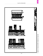
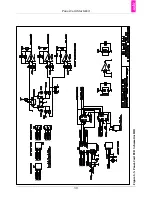
Page 32: ...Panel Card Starterkit 26 Figure 6 1 Panel Card EVB Schematics Bus JTAG ...
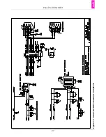
Page 33: ...Panel Card Starterkit 27 Figure 6 2 Panel Card EVB Schematics USB RS232 ...
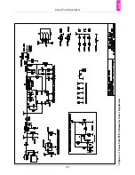
Page 34: ...Panel Card Starterkit 28 Figure 6 3 Panel Card EVB Schematics Power Regulation ...
Page 35: ...Panel Card Starterkit 29 Figure 6 4 Panel Card EVB Schematics Connectors ...
Page 36: ...Panel Card Starterkit 30 Figure 6 5 Panel Card EVB Schematics HID ...
Page 39: ...Panel Card Starterkit 33 Figure 6 8 Panel Card Connector Schematics USB Ethernet ...
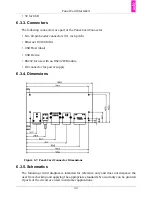
Page 49: ...Panel Card Dimensions 43 Appendix H Panel Card Dimensions Figure H 1 Panel Card 35 Dimensions ...
Page 50: ...Panel Card Dimensions 44 Figure H 2 Panel Card 57 Dimensions ...


