Hardware Description
18
Accordingly, the LCDC should not be powered down without deactivating the LCD supply
voltage. The same is true if the LCDC is stopped indirectly by stopping the respective
clock source, namely the PLLA.
The LCD backlight supply is not involved in these considerations. It may switched on or
off at any time independently of the state of the LCDC.
4.25.2. LCDC Video Memory Selection
The video memory of the LCDC is part of the working memory of the processor. It might
either reside in the internal SRAM, as well as in the external SDRAM. Using the internal
SRAM has the advantage that the LCDC can access its video memory via an autonomous
bus and does not affect the processor performance. However, as the internal SRAM has
a capacity of only 160 kBytes, the color depth for a QVGA display is only 16 bit / pixel
(320 x 240 x 2 = 153600 bytes are necessary). For a high quality display 16 bit per pixel
might not be sufficient.
On the other hand, using the SDRAM as video memory has the advantage that there is
plenty of space for all resolutions. Also the internal SRAM is now available for time critical
software sections. Of course the LCDC will now be permanently scanning its video memory
and might therefore reduce the overall performance to some degree.
4.25.3. LCDC Frame Buffer
The LCDC video memory is organized as a frame buffer in a straight forward way. It
supports color depths of 1, 2, 4, 8, 16, or 24 bit per pixel. The video data is stored in a
packed form with no unused bits in the video memory.
The color resolutions of 1, 2, 4, and 8 bpp (bits per pixel) use a palette table which is made
up of 16-bit entries. The value of each pixel in the frame buffer serves as an index into
the palette table. The value of the respective palette table entry is output to the display
by the LCDC, see Table 4.4, “LCDC palette entry”.
Bit[14..10]
Bit[9..5]
Bit[4..0]
Blue[7..3]
Green[7..3]
Red[7..3]
Table 4.4. LCDC palette entry
The bits 2..0 of each color channel are not used in the palettized configuration — they are
set to 0. The intensity bit sets the least significant valid bits of every color, that is, the bits
2, 10, and 18 of a 24-bit LCDC output word.
The same scheme as above is used in the 16-bit color resolution configuration, although
in this case the frame buffer entry is output directly to the display instead of indexing a
palette table.
In the 24-bit color resolution configuration, each frame buffer entry consists of one byte
for each color, see Table 4.5, “LCDC 24 bit memory organization”.
Bit[23..16]
Bit[15..8]
Bit[7..0]
Summary of Contents for Panel-Card
Page 1: ...Panel Card Technical Reference ...
Page 32: ...Panel Card Starterkit 26 Figure 6 1 Panel Card EVB Schematics Bus JTAG ...
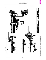
Page 33: ...Panel Card Starterkit 27 Figure 6 2 Panel Card EVB Schematics USB RS232 ...
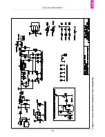
Page 34: ...Panel Card Starterkit 28 Figure 6 3 Panel Card EVB Schematics Power Regulation ...
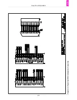
Page 35: ...Panel Card Starterkit 29 Figure 6 4 Panel Card EVB Schematics Connectors ...
Page 36: ...Panel Card Starterkit 30 Figure 6 5 Panel Card EVB Schematics HID ...
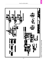
Page 39: ...Panel Card Starterkit 33 Figure 6 8 Panel Card Connector Schematics USB Ethernet ...
Page 49: ...Panel Card Dimensions 43 Appendix H Panel Card Dimensions Figure H 1 Panel Card 35 Dimensions ...
Page 50: ...Panel Card Dimensions 44 Figure H 2 Panel Card 57 Dimensions ...

