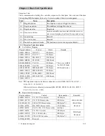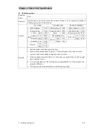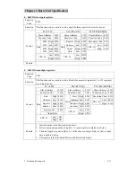
Chapter 2 Basic Unit Specification
3. Communication ports
2-14
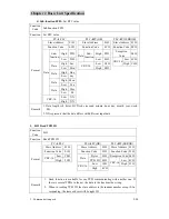
A.
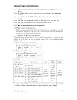
01H read coil
Function
Code
01H
Function
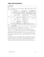
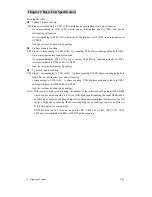
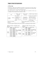
This function code is used to read from 1 to 2000 consecutive status of coils in a
remote device.
Format
PC
Æ
PLC
PLC
Æ
PC(OK) PLC
Æ
PC(ERROR)
Slave Address
01H
Slave Address 01H
Slave
Address 01H
Function Code
01H
Function Code
01H
Function Code
81H
High 00H
Bytes
03H
Exception Code 01H
Start
Address Low 13H
Output state
x32-x23
CDH
Low 80H
High 00H
Output state
x42-x33
6BH
CRC-16
High 55H
Data
Coil
number
Low 15H
Data
Output state
x47-x43
05H
Low 0EH
Low
40
CRC-16
High 90H
CRC-16
High 12
Remark
Byte count equals quantity of coils / 8, if the remainder is different of 0, add one.
It is recommended to set the start address equal multiple of 8, for that can improve the
program efficiency.
In PC
Æ
PLC, coils number is 0015(H)=21(D), however 21/8=2
……
5. Bytes number in
PLC
Æ
PC (OK) should be 2+1=3(D) =03(H) (means 3 x 8 = 24 coil states).
Address for Input coil and output coil address is octal allocated (X000~X007, X010~X017,
X020~X027 ….), in
PC
Æ
PLC,
Start Address is 0013(H)=23(Oct),in
PLC
Æ
PC(OK), the
output state should be the 24 coil state from
X023, that is 21 coils states (X024, X025, ….,
X027, X030, X031, …X036, X037, X040, X041, …, X046, X047) plus three 0s. The response
data should be three bytes (8 bits are a byte), that is X23-X32, X33-X42, X43-X47. It is the same
for reading Y.
In the Byte (X23~X32), X23 is Low significant bit and X32 is High significant bit. The byte is
arranged from High bit to Low bit, that is X32~X23. When the responding data for X032-X023 is
CD (H) = 1100 1101(B), the state for X32~X023 is ON-ON-OFF-OFF-ON-ON-OFF-ON.
Note: The maximal coil number of M/H type is 2000,the maximal coil number of S type is 960.


