background image

Chapter 2 Basic Unit Specification 

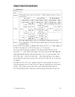
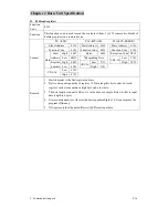
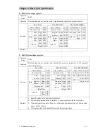
4. High speed input 


2-28

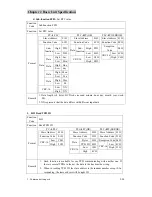
4.4.2


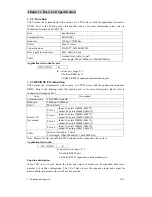
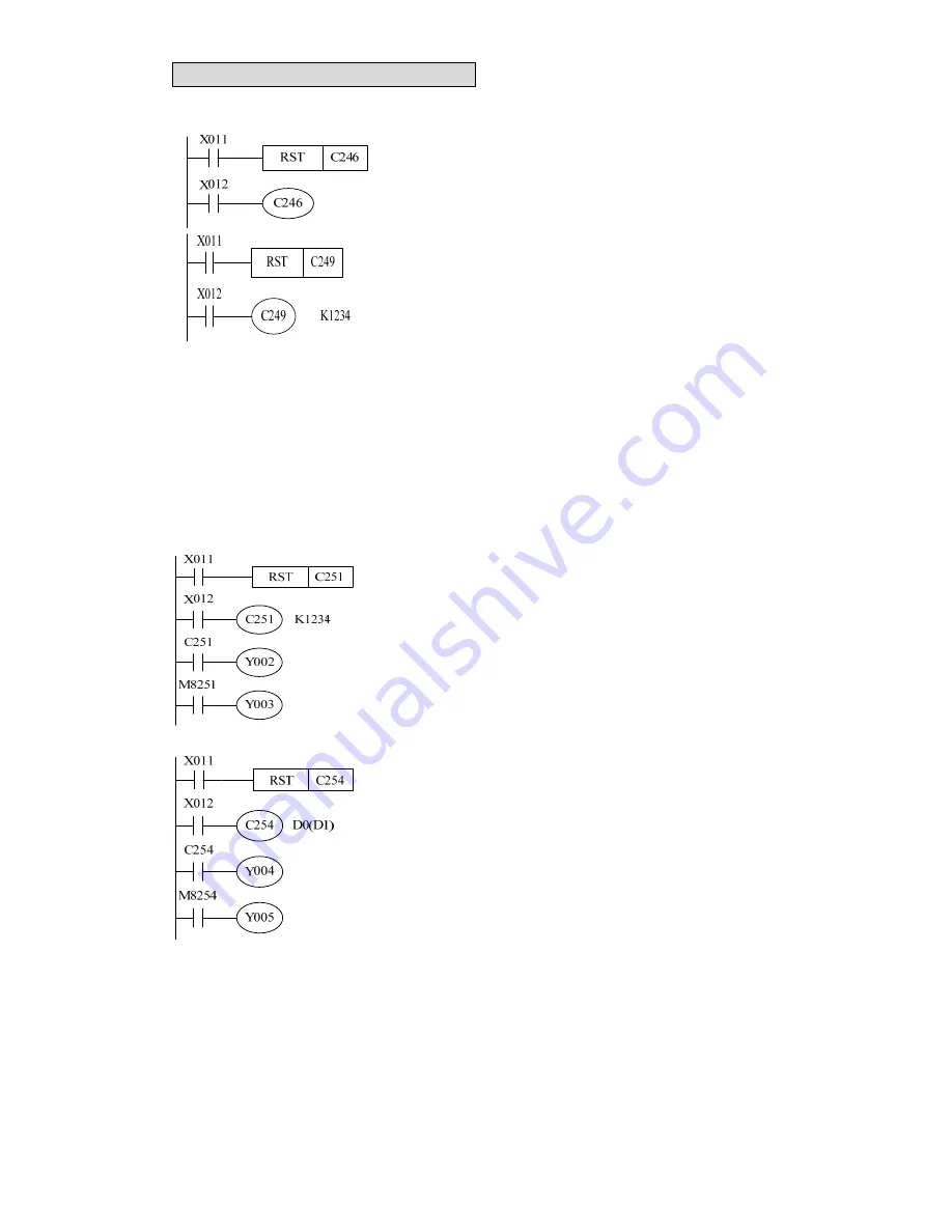
1 Phase 2 input 


‹


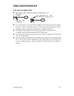
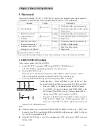
X012 is ON: C246 will operate up counting when Input 

X000 is OFF

Æ

ON, while Down counting when X001 is 

OFF

Æ

ON.  


‹


X012 is ON: C249 will start to operate up counting for 

X001, down counting for X000 when X005 is ON. 

‹


When X002 is ON, C249 will be reset at once. Sequential 

instruction RST also can do the same as left figure. 

‹


C246~C249 counting direction can be supervised by M8235~M8245. 


4.5


Application example for 2 phase high speed counter 

4.5.1


2 Phase 2 inputs 

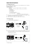
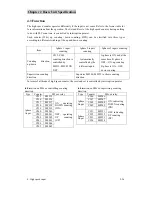
The present value and output operation of 32 bit counter is same with former 1phase 1input high 
speed counting. 


z


When X012 ON, C251 starts to count X000 (A phase), and 
X001(B phase). When X011 ON, RST instruction reset C251. 

z


If the present value is bigger than set value, Y000ON, and if 
not, Y002 OFF. 

z


When Y003 ON, counting direction is Up, or the direction is 
Down. 


z


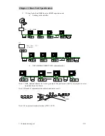
When X012 ON and X006 ON, C254 starts to count X000 (A 
phase) and X001 (B phase). 

z


When X011 ON, reset C254. And X002 also can do that. 

z


If the present value is bigger than set value, Y004 ON. 
Otherwise, Y004 will be OFF. 

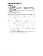
z


Y005 ON: Down counting; Y005 OFF: Up counting. 

z


When A phase is ON and B phase is change OFF to ON, the 
counting direction will be UP. Otherwise, when B is change 
ON to OFF, direction will be down. The state ON/OFF of 

M8251~M8255 can indicate the counting direction of C251~C255.   


Summary of Contents for TP03 PLC

Page 1: ...TP03 PLC USER Manual TP03 Programmable Logic Controller TECO Electric Machinery Co Ltd...

Page 2: ...Function description for 3 communication port 2 9 3 3 Three communication ports description 2 11 3 3 1 Modbus slave communication 2 11 3 3 2 Data link 2 21 3 3 3 REMOTE I O instruction 2 21 3 3 4 RS...

Page 3: ...g expansion unit 3 17 2 3 2 TP03 analog expansion unit 3 17 2 4 Wiring for analog expansion module 3 18 2 5 Electric Specification 3 20 2 5 1 TP02 4AD Specification 3 20 2 5 2 TP03 8AD Specification 3...

Page 4: ...light load 5 13 4 3 4 Lifespan of relay 5 13 4 3 5 Wiring consideration for TP03 HT type PLC 5 13 5 Solving noise problem 5 14 5 1 Power source noise 5 14 5 2 Solving thunder stroke problem 5 15 5 3 A...

Page 5: ...lags D 8 4 Interruption disable M 8 4 UP DOWN counting set device M 8 4 Devices M 8 6 Error detection D 8 6 Communication and link M I 8 6 Communication and link D I 8 8 Communication and link M II 8...

Page 6: ...uct type 1 3 2 1 Basic module list 1 3 2 2 Expansion module list 1 6 2 3 Programming tool 1 8 2 4 Accessory list 1 9 3 System configuration 1 10 4 OP07 08 TP03 cable TP03 302MC specification 1 11 5 TP...

Page 7: ...3s Each PLC can receive max 64 bits 8 words 15 data Remote I O TP03 is set as master it can control as much as 4 other TP03s Each slaver has MAX input 36 points output 24 points Compliant with Modbus...

Page 8: ...on module Analog expansion module Type No description TP03 32 E M R Input Output type D 24VDC Input Module type is X only R Relay Output T NPN transistor Module type M 24VDC input point and output poi...

Page 9: ...92 64mm See Fig3 177 92 64mm See Fig4 TP03 30MR A 16 14 TP03 20HR A 12 8 TP03 30HR A 300mA 16 14 116 90 83mm See Fig1 TP03 40HR A 24 16 TP03 60HR A 85 264 VAC 500mA 36 24 TP03 40HR D 24 16 TP03 60HR...

Page 10: ...Model TP03 60HR A VX X Power 100 240VAC 50 60Hz 50VAmax Input 24VDC 7mA Output 250VAC 2A DC30V 2A AUX Output 24VDC 500mAmax Input speci fi cati on O utput speci fi cati on Auxi l i ary pow er output...

Page 11: ...3 Run stop switch 4 2 groups of potentiometer 5 PC PDA communication port 6 Expansion port 7 Battery 8 Memory pack port 9 Input terminal block 10 Running indicator 11 Input and output indicator 12 Exp...

Page 12: ...dard cover Fig 6 TP03 1OP Compact timer and counter setting device In developing Fig 7 TP03 6AV Analog potentiometer input port 6 In developing Fig 8 TP03 2TI Timer 0 30S input port 2 In developing Fi...

Page 13: ...03 2DA 0 2 10v 20mA analog output 2 channel Fig 18 TP03 3MA 2 1 20mA analog input 2 channel 20mA analog output 1 channel Fig 18 TP03 8AD 24Vdc 8 0 20mA analog input 8 channel 57 x 90 x 83 mm Fig 14 Fi...

Page 14: ...g 21 Profile referring figure TP03 DNET Fig 19 TP03 PBUS Fig 20 EN01 Fig 21 2 3 Programming tool Type No Description Remark TP03 PC TP03 PLC PC software Fig 23 TP03 PDA TP03 PLC PDA software The type...

Page 15: ...ilt in 6cm cable for expansion module Fig 26 TP03 304EC TP03 expansion module Option 40cm cable for expansion module Fig 26 TP03 340EC 26 pins Only for TP03 expansion module 1 8M cable black Fig 27 TP...

Page 16: ...A SHLD C7 C8 C5 C6 V7 V8 V5 V6 C4 C3 C2 C1 0V V4 V3 V2 V1 24V PWR RUN Basic module TP03 40 60 TP03 20 30 Expansion cable TP03 304EC 4cm TP03 340EC 40cm Terminal connector TP 200EC TP03 16EMR TP03 16EY...

Page 17: ...nnection D SUB 9pin Female OP07 08 MINI DIN 8pin Male TP03 PG PC PDA port definition pin pin definition N C 1 TX 2 2 RX RX 3 7 TX N C 4 6 GND GND 5 3 GND N C 9 8 GND Vcc 6 5 Vcc TX 7 1 RX 8 4 RX TX 6...

Page 18: ...ition and internal connection D SUB 9pin Female MINI DIN 8pin Male TP03 PG PC PDA port definition pin pin definition RX 2 4 TX TX 3 1 RX GND 5 3 GND 6 GND 8 GND 5 Vcc 7 TX 2 RX 6 1 4 7 2 3 8 5 9 3 6 4...

Page 19: ...l block INPUT COM COM 0 1 2 3 4 5 6 7 OUTP UT COM0 0 1 2 3 COM1 4 5 6 7 TP03 14SR A COM M 24V 0V SG B A INPUT COM A COM A 0 1 2 3 4 5 6 7 10 11 12 13 OUTP UT COMB 0 1 2 3 COMC 4 5 6 7 TP03 20SR A COM...

Page 20: ...VAC A SG 3 0 COM1 1 2 5 6 COM2 4 Input 10 3 5 7 1 COM 0V COM 24V 0 2 6 4 17 11 13 15 12 14 16 TP03 30HR A Output 7 100 240VAC L N 3 5 6 0 COM1 COM0 B A SG 1 2 COM2 4 15 10 COM3 13 11 12 14 Input 10 CO...

Page 21: ...27 TP03 40HR D Output 7 COM0 A B SG 24VDC 4 2 1 3 COM1 0 5 6 COM2 17 14 12 11 13 COM3 10 15 16 COM4 Input 15 3 1 COM COM 0 2 7 11 13 5 10 4 6 12 14 40 27 23 25 17 21 22 16 20 24 26 37 33 31 35 34 30...

Page 22: ...instruction 2 21 3 3 4 RS MBUS instruction 2 22 3 4 Wiring methods 2 22 4 High speed counter 2 24 4 1 General characteristic of high speed counter 2 24 4 2 Number for Built in high speed counter 2 24...

Page 23: ...DA 3 1 x TP02 4AD 1 Xtp02 2DA 7 x TP03 8AD 4 x TP03 2DA Max Analog I O 8 input channels 2 output channels 60 input channels 10 output channels 36 ANB ORB ect 0 62 s step ANB ORB e ct 0 31 s step Basic...

Page 24: ...ng to I00 I30 Minimum pulse width 100 s 6points corresponding to I00 I50 Minimum pulse width 100 s 6points corresponding to I00 I50 Minimum pulse width 10 s Pulse output N A 2 points Y0 Y1 with accele...

Page 25: ...Power supply specification Type Item 14S 20S 26S 36S 20M 30M 20H 30H 40H 60H 24Vdc terminal for external using 250mA with short circuit protection 300 mA with short circuit protection 500 mA with shor...

Page 26: ...nal block Can expand 32 points and expand 2 x TP02 AD units and 1 x TP02 2DA unit or 1 TP03 AD unit and 1 DA unit TP03 H Type 40 60 points Built in EEPROM 16 000 Steps Built in RTC RS485 communication...

Page 27: ...il 10 to 57Hz amplitude 0 075mm 57 to 150Hz acceleration 9 8m sec2 1G Lloyd s 2 hours per axis on each of three mutually perpendicular axis When mounted on a panel surface 2 to 25Hz amplitude 1 6mm 25...

Page 28: ...s schematic diagram Current 2A 1 point 5A COM Voltage 250VAC 30VDC or less Inductive 100VA Max load resistive 120W Min Load DC5V 1mA Off On 6ms Responding time On Off 6ms B Transistor Transistor outpu...

Page 29: ...start from X50 D8436 and so on WhileWhile the output should be start from Y30 D8381 and so on For instance If the user plans the following system the number arrangement for I O is suggested in the tab...

Page 30: ...V 2 4 0 COM 0V COM 3 1 5 10 12 14 16 11 7 13 17 15 Note 1 The baud rate for PC PDA port is 9 6k 57 6kbps Note 2 The baud rate for expansion cards and RS485 port is 9 6k 307 2kbps Note 3 The default ba...

Page 31: ...tion It must be used together with application instruction F191 refer to 3 3 3 and instruction description F191 E RS instruction The two ports can be enabled simulataneously for such function and comm...

Page 32: ...o parity 0 1 odd parity check 1 1 even parity Stop bit B3 0 1bit 1 2bit Baud rate Kbps B7 B6 B5 B4 0 0 1 0 300 0 0 1 1 600 0 1 0 0 1200 0 1 0 1 2400 0 1 1 0 4800 0 1 1 1 9600 1 0 0 0 19200 1 0 0 1 384...

Page 33: ...When TP03 receives command from PC TP03 will perform according to the command and then feedback to PC If there is an error in command content TP03 will feedback an exception response to PC z Command...

Page 34: ...Points 0200H 07FFH M0 M1535 1536 Points 0800H 0BFFH S0 S1023 1024 Points 0C00H 0DFFH T0 T511 512 Points 0E00H 0EFFH C0 C255 256 Points 0F00H 0FFFH M8000 M8255 256 Points 1000H 10FFH M8256 M8511 256 Po...

Page 35: ...e High word High byte High word Low byte 4336H C255 Low byte of present value Low word High byte Low word Low byte Present value 4337H C255 High byte of present value High word High byte High word Low...

Page 36: ...f 8 for that can improve the program efficiency In PC PLC coils number is 0015 H 21 D however 21 8 2 5 Bytes number in PLC PC OK should be 2 1 3 D 03 H means 3 x 8 24 coil states Address for Input coi...

Page 37: ...oils Function Code 0FH Function This function code is used to force each coil in a sequence of coils from 1 to 1968 to either ON or OFF in a remote device Format PC PLC PLC PC OK PLC PC ERROR Slave Ad...

Page 38: ...02H Start Address Low 6BH Responding Data Low C1H High 00H Low XX CRC 16 High 34H Data Register number Low 03H CRC 16 High XX Low 63H CRC 16 High 47H Remark 1 Start character is the first register ad...

Page 39: ...Function This function code is used to write a block of consecutive registers 1 to 125 registers in a remote device Format PC PLC PLC PC OK PLC PC ERROR Slave Address 01H Slave Address 01H Slave Addre...

Page 40: ...igh A5H High A5H CRC 16 Low C1H Data Data Low 37H Data Data Low 37H Low DAH Low DAH CRC 16 High 8DH CRC 16 High 8DH Remark Data is a random word H 6CH PLC control 6CH RUN STOP program Write ID and Rea...

Page 41: ...yte must be set to 0 2 If the TP03 is initialized the ID will be reset to 001 If you want to set up a net it is necessary to set a new ID for each PLC c Sub function FF02 Read TP03 running stopping st...

Page 42: ...Remark 1 Data length is 8 bytes BCD code second minute hour day month year week 00 2 XX represents that the data differs with different input data I 01H Read TP03 ID Function Code 01H Function Read TP...

Page 43: ...ing about this function and as for more information please refer to Instruction Description F191 Item Description communication EIA RS485 standard Baud rate 9600bps 614400bps Slave Max 4 slaves Slave...

Page 44: ...expansion communication port z RS instruction needs no communication protocol Data communication is available for other communication unit including PC barcode reader and printer z MBUS instruction is...

Page 45: ...expansion card a Linking with controller Or b DATA LINK REMOTE I O communication Note 1 SHL terminal should be 3 class ground or the production will be interrupted to error operation because of noise...

Page 46: ...ng data would be wrong 4 2 Number for Built in high speed counter The number is as following TP03M H type 1phase 1 input counting 1phase 2 inputs counting 2phases 2 inputs counting C235 C236 C237 C238...

Page 47: ...005 And the rest may be deduced by analogy 2 phases 2 inputs counting X000 input corresponding to C251 A B A phase counting C246 B phase counting defaults to X001 has no interruption reset and set fun...

Page 48: ...tomatically controlled by the different inputs A phase is ON and at the same time B phase is OFF ON up counting B phase is ON OFF down counting Supervision counting direction Supervise M8246 M8255 to...

Page 49: ...83 647 will change to 2 147 483 648 as up counting is operated also the value 2 147 483 648will change to 2 147 483 647 as down counting is operated z When X011 is enabled the instruction RST will be...

Page 50: ...r is same with former 1phase 1input high speed counting z When X012 ON C251 starts to count X000 A phase and X001 B phase When X011 ON RST instruction reset C251 z If the present value is bigger than...

Page 51: ...1 present value K20 Y002 ON Regarding to general application instruction F10 CMP and FNC11 ZCP there will be a delay because of PLC scan time In order to avoid that delay in high speed counting the ab...

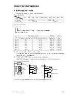
Page 52: ...able device for high speed counter The enabling relay for high speed counter can not be shared with other instructions For instance input interruption pointer and F56 SPD speed detect Even the present...

Page 53: ...I200 M8052 M8172 X003 I301 I300 M8053 M8173 X004 I401 I400 M8054 M8174 X005 I501 I500 M8055 M8175 z The pointer number can not be used repeatedly As for the same input the corresponding rising edge i...

Page 54: ...tput 24VDC Note Such function should be done by above application instructions and only transistor output type is available If relay output type is set such function the output will be error for the l...

Page 55: ...coil of accumulating timer T 3 Contact counting coil and reset coil of retentive counter and high speed counter 4 Retentive register D for present value 5 Register for present value of accumulating an...

Page 56: ...3 PDA refer to TP3 PC TP3 PDA programming method for more information B Built in RUN STOP switch When the switch is turned to RUN position TP03 will RUN while it is turned to STOP TP03 will stop Such...

Page 57: ...write timing data 7 F169 HOUR set the timer Tolerance N A 45seconds month 25 Leap year N A Auto offset Flash memory retentive N A D8013 D8019 data will be kept by lithium battery when power fails Set...

Page 58: ...ue can be multified with the application instruction F22 F22M UL D0 K2 D10 M 8000 T0 D10 Transfer the data data in D2 2 to D10 D11 The multiplication instruction can expand the register data so the se...

Page 59: ...unction TP03 can Run at without battery mode Although TP03 is set to Run without battery mode and the battery is not installed or has no power the BAT LED will not be OFF Run without battery Example f...

Page 60: ...3 2 1 Introduction 3 13 2 1 1 Brief 3 13 2 1 2 Data register and channel of analog expansion module 3 14 2 1 3 Setting the system memory 3 15 2 2 General Specification for analog expansion unit 3 17 2...

Page 61: ...rosive gas Altitude Operation 0 to 2 000m 0 to 6 565 feet Transport 0 to 3 000m 0 to 9 840 feet Vibration Resistance Mounted on a DIN rail 10 to 57Hz amplitude 0 075mm 57 to 150Hz acceleration 9 8m se...

Page 62: ...sion 1 2 1 TP02 digital expansion unit I 1 2 2 TP02 digital expansion unit II COMA 16 COMe 7 2 4 5 1 6 COMc 3 12 COMb 10 15 13 8 9 11 14 COMd 1 9 5 7 3 15 13 11 8 4 2 COMA 6 COMA COMA 16 12 10 14 1 2...

Page 63: ...COMA COMA 3 1 2 5 3 4 6 7 8 8 7 5 6 Downside terminal block Internal circuit Symbol content 1 8 Input terminal Terminal block COM A COM B Common terminal Note a 8 inputs share one common terminal b T...

Page 64: ...d 1 mA 5vDC Indicator LED LIT when output ON Output Insulation Relay Internal power supply Consumption current For 5VDC max 50mA For 24VDC max 80mA Accessory Expansion cable TP 042EC 4cm 14pin Upside...

Page 65: ...put Insulation method Photo coupling insulation Internal power supply Current consumption For 5VDC Max 50mA For 24VDC Max 80mA accessory Expansion cable TP 042EC 4cm 14pin Upside terminal block 8 1 3...

Page 66: ...ve 20Vdc 3 5mA min OFF level Below 8Vdc 1 5mA max Responding time 10ms Indicator LED lit when input ON Input Insulation method Photo coupling insulation Internal power supply Current consumption For 5...

Page 67: ...8Vdc 1 5mA Responding time 10ms Indicator LED lit when input ON input Insulation method Photo coupling insulation Internal power supply Current consumption For 5VDC Max 50mA For 24VDC Max 80mA Upside...

Page 68: ...w 9 Vdc 2 5mA Responding time 10ms Indicator LED lit when input ON Input Insulation method Photo coupling insulation PWR LED 5V Power LED Green OE LED Output Enable LED Green Internal power supply Cur...

Page 69: ...or LED lit when input ON Input Insulation method Photo coupling insulation PWR LED 5V Power LED Green OE LED Output Enable LED Green Internal power supply Current consumption For 5VDC Max 30mA For 24V...

Page 70: ...ethod Relay PWR LED 5V Power LED Green OE LED Output Enable LED Green Internal power supply Current consumption For 5VDC Max 40mA For 24VDC Max 85mA 7 5 2 0 COMD 3 COMC 1 4 6 5 4 7 6 7 PWR 1 0 3 OE 2...

Page 71: ...LED Output Enable LED Green Internal power supply Current consumption For 5VDC Max 30mA For 24VDC Max 45mA 7 5 2 0 COMD 3 COMC 1 4 6 5 4 7 6 7 PWR 1 0 3 OE 2 3 COMA 1 0 2 4 6 COMB 5 5 4 6 7 0 1 2 3 OU...

Page 72: ...ling insulation PWR LED 5V Power LED Green Internal power supply Current consumption For 5VDC Max 30mA For 24VDC Max 45mA 1 3 5 7 COMB COMB COMA 0 2 4 6 6 4 5 7 2 0 1 PWR 3 3 2 0 COMA 1 6 4 5 7 3 0 1...

Page 73: ...hannels and 4 analog output expansion units if installed with 4 TP03 2DAs the system will have 8 output channels That is to say the system can expanse so much to 60 channels of analog input and 10 cha...

Page 74: ...ue to different application refer to 3 2 1 2 Data register and channel of analog expansion module System will read data in the channel and write them in the data address Analog expansion module for in...

Page 75: ...53 56 D8275 AD Channel 57 60 D8276 Operation mode for AD module to set 4 HEX codes Hxxxx in Register D8261 D8276 0 AD mode is disabled 1 0 10V voltage input mode 0 4000 2 0 20mA current input mode 0...

Page 76: ...imes Sampling the 5 consecutive data from mode 2 then get the average of the max and min data For example sampling data 1 161 sampling data2 120 sampling data3 154 sampling data4 160 sampling data5 19...

Page 77: ...Installation Install directly or DIN rail Ground Less than100 ohm Insulation system Photo coupling isolation Insulation impedance 10M or above 500V DC between output terminal and secondary circuit Wit...

Page 78: ...et or the analog unit will be damaged Wiring figure of Output D A analog expansion module 1 The cable for analog input should be standard isolated twisted cable routed away power line and other line w...

Page 79: ...Chapter 3 Expansion unit specification expansion unit 3 19...

Page 80: ...oltage input terminals for Voltage signal between V C I1 I4 Current input terminals for Current signal between I C and short circuit V I C1 C4 V or I Common terminal SHLD Please connect Shielded termi...

Page 81: ...C0 C7 Common terminal for A0 A7 SHLD Please connect Shielded terminal to FG on the House And all shielded terminals are internally connected 24V 24VDC input terminal Terminal block 0V 24VDC input term...

Page 82: ...Channel A0 A3 Thermistor Pt100 signal input A B0 B3 Thermistor Pt100 signal input B B0 b3 Thermistor Pt100 signal input b 24V 24VDC input terminal Terminal block 0V 24VDC input terminal Power indicato...

Page 83: ...inal 24V 24VDCPower input terminal Terminal block 0V 24VDCPower input terminal Power indicator PWR 24 V Power LED Green LNK Link LED Green internal power 5VDC Max current 50mA External power 24VDC 20...

Page 84: ...Common ground V1 V2 Voltage output terminal output voltage signal 10V 10V between V and C terminal V1 V2 and V1 V2 can not be used at same time C3 C4 Common ground I1 I2 output terminals for Current s...

Page 85: ...V0 V1 Voltage output terminal output voltage signal between terminal V and C I0 I1 Current output terminal output current signal between terminal I and C C0 C1 Common ground for V0 V2 I0 I2 V0 V1 Vol...

Page 86: ...1 or less 0 55 Transmission speed 1scan time 3 Channel Vin0 Vin1 Voltage output terminal output voltage signal between terminal V and C Iin0 Iin1 Current input terminals for Current signal between I C...

Page 87: ...Chapter 3 Expansion unit specification expansion unit 3 27 Principle figure Input circuit Output circuit...

Page 88: ...unit Digital I O base unit expansion unit Channels of AD Channels of DA S type 80 8 2 20 30 M type 128 8 2 20 30 H type 256 8 2 40 60 H type 256 60 10 3 2 Power consumption 3 2 1 5V power provide by...

Page 89: ...e same time Current of 24v internal mA Relay output 30 150 Transistor output of expansion unit 0 0 Total 150 The third step accomplish the table 3 2 3 If there are OK all then can judge the TP03s are...

Page 90: ...2 TP02 expansion unit 4 2 1 3 TP03 expansion unit and power unit 4 3 1 4 TP03 communication unit 4 3 2 Installation 4 5 2 1 Ambient environment 4 5 2 2 Installation of basic unit and expansion unit 4...

Page 91: ...imension 4 1 Chapter4 Dimension and installation 1 Outline dimension 1 1 Basic unit TP03 14SR A 14 20 TP03 20SR A TP03 26SR A 26 36 TP03 36SR A TP03 20MR A TP03 20HR A TP03 20MT A TP03 20HT A 20 30 TP...

Page 92: ...40HT A TP03 40HR D 40 60 TP03 60HR A TP03 60HT A TP03 60HR D 1 2 TP02 expansion unit TP02 16EXD TP02 16EYR TP02 16EYT TP02 16EMR TP02 4AD TP02 2DA TP02 32EMR 14 10 12 16 COMA 6 COMA 2 4 8 COMb 8 3 COM...

Page 93: ...ower unit TP03 16EMR A TP03 16EMT TP03 16EYR TP03 16EYT TP03 16EXD TP03 2DA TP03 3MA TP03 8AD TP03 4TM TP03 4RD TP03 01SPS A TP03 4TM TP03 2DA TP03 3MA TP03 8AD TP03 01SPS TP03 16EMR TP03 16EYR TP03 1...

Page 94: ...following occasions Ambient temperature exceeding 0 55 Rel ative humidity exceeding 5 90 RH Dusty salty iron powders place corrosive flammable or ignescent gas Exposed to volatile gas detergent ammon...

Page 95: ...M4 15mm or bigger screws to fix the PLC in the distributors When the expansion cable 4cm is used please refer to 6 1 for installation dimension and use M4 screws to fix the units z Basic unit TP03 20...

Page 96: ...c 4 2 1 3 COMA 2 4 1 COMA COMA COMA 3 5 13 15 10 12 5 7 COMd COMb 8 6 11 9 16 14 COMe 14 10 12 6 8 7 9 11 13 16 15 20mm 20mm The following figure indicates dimension for installation holes when expans...

Page 97: ...ottom to outside The module will be uninstalled easily 2 3 Installation for expansion cable and termination connector The expansion cable is used for expanding expansion modules The expansion capabili...

Page 98: ...ion connector originally installed the basic module at right side 3 Plug the expansion connector to the male connector on the module 4 Then plug the other end connector to the male connector at left s...

Page 99: ...lt in DC24V power supply share Common terminal with External power 5 9 4 2 Wiring consideration for Input terminal 5 9 4 2 1 Wiring consideration for different Input devices sensor switch 5 10 4 2 2 L...

Page 100: ...t input signal of both basic and expansion units are susceptible to interrupting by noise Thusly the distance should be more than 50mm as above figure The basic unit can expand more than two expansion...

Page 101: ...power fail or lower voltage will stop the PLC and cut all the output And the PLC will recover operation as long as the power becomes normal There are many retentive registers and relay for keeping th...

Page 102: ...in the system Any fault will result in all the industry automation system out of control or in risk It is recommended connecting a protection circuit to Power input 1 SG B A 1 SG B A COM0 COM0 24VDC 2...

Page 103: ...C input SINK and SOURCE mode Sink current inputs share the common Source Current outputs share the common Wiring A SINK mode Input equivalent circuit Wiring circuit SB SOURCE mode Input equivalent cir...

Page 104: ...output PLC internal circuit is photo coupling insulated For relay output PLC internal circuit is relay insulated 4 Please pay attention to common terminal s wiring for output Take TP03 30MT A as an ex...

Page 105: ...t lamp resistance load Mutually locked Output to connect an external mutually locked circuit matching with PLC internal program to provide safety protection for any exceptional condition Wiring exampl...

Page 106: ...1 Power COMA COMA 4 2 8 6 3 5 7 Power COMB COMB 5 3 7 1 4 2 8 6 TP02 16EMR 1 Power COMA COMA 4 2 8 6 3 5 7 TP02 32EMR 7 Power COMA COMA COMA COMA 2 4 6 1 5 3 16 12 10 8 14 11 9 13 15 TP03 16EXD Power...

Page 107: ...MR 1 7 6 3 COMC Power COMD 4 2 8 5 Power TP02 32EMR Power C O M b 1 6 C O M c 3 8 L L L L 2 4 7 5 L Power L L L 16 9 11 14 C O M d L L L L 12 10 15 13 Power C O M e L L Power L L TP03 16EYR TP03 16EYT...

Page 108: ...ower supply share Common terminal Note All external power DC24V terminals can be connected with the COM while terminal must be separated 4 2 Wiring consideration for Input terminal Input ON OFF durati...

Page 109: ...e 5 NPN current output type Example 6 PNP current output type Example 7 Voltage output type Among the above example 1 2 3 4 5 the driving current of external output transistor must be larger than that...

Page 110: ...ating the effect of leakage current the resistance of R should comply with the following formulation VinOFF R Rin R Rin iL Q toleranceA Vinoff iL Rin Rin VinOFF R Tolerance A 0 7 Power for bleeder res...

Page 111: ...arge 4 3 2 Surge voltage of inductive load When inductive load is ON OFF transited there will be a surge voltage KV Particularly relay output module has no standard surge absorber so it might be serio...

Page 112: ...n of relay Note 2 Mechanical lifespan of the relay will be over 200 million times Note 3 Generally the lifespan of relay could be over 100 000 times as the current is within 2A 4 3 5 Wiring considerat...

Page 113: ...If the system can not be grounded separately just connect the terminal of TP03 to the distributing box as shown in figure The connecting wire should be as short as possible If the distributing box ha...

Page 114: ...single one when noise is very serious And several transformers are recommended pri m ary si de 110V 100V 90V 0V AC Power supply For TP03 power supply terminals For Load MCCB 5 2 Solving thunder strok...

Page 115: ...magnetic switch The system expansion cable must not be placed into the same wiring duct with any other input output signal or power line 5 4 Anti Noise for I O Wiring Please apply insulated twisted pa...

Page 116: ...1 3 Expansion units 6 3 3 Troubleshooting 6 4 3 1 LED indicator status 6 4 3 2 Presumption of troubleshooting procedure 6 4 3 3 Preparation for troubleshooting 6 4 3 4 Check the following again 6 5 3...

Page 117: ...l or close to high voltage high current lines Are output lines equipped with protection fuses Are shielded twisted pair cables used for communication lines 3 Check expansion cables and termination con...

Page 118: ...is right If either BAT or ERR indicator is on please refer to troubleshooting 4 All initialize With PDA PC to initialize TP03 and write program to it 5 Check the wiring to I O Check the input wiring w...

Page 119: ...oltage of input terminal on the terminal block Whether it is within specified range DC19 2 26 4V Output terminal voltage Measure voltage of output terminal on the terminal block Whether it is within s...

Page 120: ...F Troubleshooting procedure 2 ON Shine slowly 6 4s Self diagnosis detects error that program does not operate and all I O does not work Troubleshooting procedure 1 ON Shine quickly 1 6s Stop mode Trou...

Page 121: ...tor If the ERROR indicator does not blink that means the program is right And the program can be trial run then It is available for user to enforce terminal ON or OFF with PC PDA to inspect wiring Run...

Page 122: ...nd parameter is not corresponding 6402 register capacity set error 6409 other error N 8065 Syntax error 8065 Error code 0000 no error 6501 instruction address error 6504 pointer repeated 6505 device a...

Page 123: ...740 PID sampling time scan cycle 6742 Overflow of variational value about measuring in PID 6743 Overflow of deviated value in PID 6744 Overflow of integration computation in PID 6745 Overflow of diffe...

Page 124: ...input terminal as switch and proximity switch 4 Add an external 24vDC power supply to input terminal and common terminals z The input indicator should be ON z The input indicator should be OFF as the...

Page 125: ...relay output type related to error 3 Check When output is ON the indicator should be lit and voltage between output will be below 1 2V When output is OFF the indicator should be OFF and voltage betwe...

Page 126: ...Instruction list 7 0 Chapter 7 Instruction List 7 1 1 Basic sequential instruction 7 1 2 Step instruction STL RET 7 2 3 Application instruction list 7 3...

Page 127: ...lly closed contacts 1 LDP Initial logical operation Rising edge pulse 2 LDF Initial logical operation Falling trailing edge pulse 2 ANDP Serial connection of Rising edge pulse 2 ANDF Serial connection...

Page 128: ...or counter coils 2 SET Sets a bit device permanently ON Y M 1 S special M 2 T C 2 special D 3 RST Resets a bit device permanently OFF Y M 1 S special M 2 T C 2 D V Z special D 3 SMCS Master control s...

Page 129: ...16 32 9 5 15 BMOV Block move 16 7 16 FMOV Fill move 16 32 13 7 17 XCH Exchange 16 32 9 5 18 BCD BCD binary coded decimal 16 32 9 5 Move and compare 19 BIN BIN binary 16 32 9 5 20 ADD Addition 16 32 13...

Page 130: ...reset 32 13 55 HSZ High speed counter zone compare 32 17 56 SPD Speed detect 16 7 57 PLSY Pulse Y output 16 32 13 7 58 PWM Pulse width modulation 16 7 High speed processing 59 PLSR Ramp pulse output 1...

Page 131: ...ESUB Float subtract 32 13 122 EMUL Float multiplication 32 13 123 EDIV Float division 32 13 127 ESQR Float square root 32 9 129 INT Float integer 16 32 9 5 130 SIN Sine 32 9 131 COS cosine 32 9 132 TA...

Page 132: ...e I O 16 3 communication 192 TEXT OP07 08 text 16 7 224 LD S1 S2 16 32 9 5 225 LD S1 S2 16 32 9 5 226 LD S1 S2 16 32 9 5 228 LD S1 S2 16 32 9 5 229 LD S1 S2 16 32 9 5 230 LD S1 S2 16 32 9 5 232 AND S1...

Page 133: ...M 8 3 Step ladder flags D 8 4 Interruption disable M 8 4 UP DOWN counting set device M 8 4 Devices M 8 6 Error detection D 8 6 Communication and link M I 8 6 Communication and link D I 8 8 Communicat...

Page 134: ...period oscillator 5ms ON 5ms OFF 8012 100ms period oscillator 50ms ON 50ms OFF 8013 1s period oscillator 0 5s ON 0 5s OFF 8014 1min period oscillator 30s ON 30s OFF 8015 Clock stop and set Stop timin...

Page 135: ...on 8001 TP03 type 0x 8002 Version 10 represents 1 0 version 8004 Error code 8005 Warning code Device No Function Operation 8010 Present scan time 1ms unit 8011 Min scan time 8012 Max scan time 8013 Se...

Page 136: ...n mode When M8035 on the No of X input which D8035 specified can be used for RUN control 8036 Enforced Run instruction When M8036 on the PLC will switch into RUN 8037 Enforced Stop instruction When M8...

Page 137: ...set for C210 8211 UP DOWN counting set for C211 8212 UP DOWN counting set for C212 Device No Function Operation 8040 8041 8042 8043 8044 8045 8046 8047 Address for ON State 8048 8049 The minimum addr...

Page 138: ...for C227 8228 UP DOWN counting set for C228 8229 UP DOWN counting set for C229 8230 UP DOWN counting set for C230 8231 UP DOWN counting set for C231 8232 UP DOWN counting set for C232 8233 UP DOWN cou...

Page 139: ...t MBUS instruction error MBUS 8129 RS485 communication port communication over time RS MBUS Device No Function Operation 8060 Expansion card error 8061 PLC hardware check PLC hardware error 8063 Commu...

Page 140: ...sion error slave 3 8340 RMIO data transmission error slave 4 8341 Expansion communication port is under RMIO 8342 RS 485 communication port is under RMIO Device No Function Operation 8321 Expansion co...

Page 141: ...munication port RS instruction 03Hex 8129 Communication watchdog time RS485 communication port RS and MBUS instruction Device No Function Operation 8320 Communication format Expansion communication po...

Page 142: ...8379 RMIO retry times 8380 RMIO monitor time 8331 Current scan time 8332 Max scan time 8333 Error counting number master 8334 Error counting number slave 1 8335 Error counting number slave 2 8336 Err...

Page 143: ...e 4 8405 Data sending error slave 5 8406 Data sending error slave 6 8407 Data sending error slave 7 8408 Data sending error slave 8 8409 Data sending error slave 9 8410 Data sending error slave 10 841...

Page 144: ...code master 8420 Error code slave 1 8421 Error code slave2 8422 Error code slave3 8423 Error code slave4 8424 Error code slave5 8425 Error code slave6 8426 Error code slave7 8427 Error code slave8 842...

Page 145: ...8 Reserved 8139 Reserved 8140 FNC156 ZRN CLR signal output enable 8141 Reserved 8142 Reserved 8143 Y000 pulse output finished Available since V1 6 8144 Y001 pulse output finished Available since V1 6...

Page 146: ...able when the PLSY operation has been enabled 8132 Frequency HSZ PLSY 8134 Target pulse 8136 Accumulated value for output pulse of Y000 and Y001 8140 F57 59 PLSR Accumulated value for output pulse of...

Page 147: ...ey F1 8281 Key F2 8282 Key F3 8283 Key F4 8284 Key F5 8285 Key F6 8286 Key F7 8287 Key F8 8288 Key F9 8289 Key F10 8290 Key F11 8291 Key F12 8292 Up 8293 Down 8294 Left 8295 Right 8296 Key TMR 8297 Ke...

Page 148: ...OP07 08 present display mode 8286 OP07 08 display number range 8287 Error code 8288 8289 Present number for timer mode 8290 Present number for Counter mode 8291 Present number for user mode1 8292 Pres...

Page 149: ...et 8264 AD13 16 channel mode set 8265 AD17 20 channel mode set 8266 AD21 24 channel mode set 8267 AD25 28 channel mode set 8268 AD29 32 channel mode set 8269 AD33 36 channel mode set 8270 AD37 40 chan...

Page 150: ...4 AD channel 9 data 8445 AD channel 10 data 8446 AD channel 11 data 8447 AD channel 12 data 8448 AD channel 13 data 8449 AD channel 14 data 8450 AD channel 15 data 8451 AD channel 16 data 8452 AD chan...

Page 151: ...channel 42 data 8478 AD channel 43 data 8479 AD channel 44 data 8480 AD channel 45 data 8481 AD channel 46 data 8482 AD channel 47 data 8483 AD channel 48 data 8484 AD channel 49 data 8485 AD channel...

Page 152: ......

Reviews: