Virtex-6 FPGA System Monitor
23
UG370 (v1.1) June 14, 2010
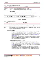
Register File Interface
JTAG DRP Commands
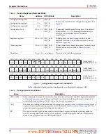
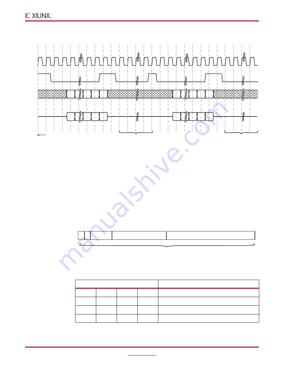
The data shifted into the 32-bit SYSMON DR during a DR-scan operation instructs the
arbitrator to carry out a Write, Read, or no operation on the System Monitor DRP.
shows the data format of the JTAG DRP command loaded into the SYSMON DR. The first
16 LSBs of SYSMON DR [15:0] contain the DRP register data. For both Read/Write
operations, the address bits SYSMON DR [25:16] hold the DRP target register address. The
command bits SYSMON DR [29:26] are used to specify a Read/Write or no operation (see
X-Ref Target - Figure 11
Figure 11:
System Monitor JTAG DRP Read Operation
TCK
TMS
TDI
TDO
Idle to allow DRP Read
to complete before
shifting out result
Idle to allow DRP Read
to complete before
shifting out result
0
31
30
MSB
MSB
LSB
LSB
Old DRP Write or New
Read Data shfited out
Read Command shifted into
SYSMON DR
0
31
30
MSB
MSB
LSB
LSB
New DRP Read Data
shifted out
Read Command shifted into
SYSMON DR
RTI
UIR
RTI RTI
RTI RTI RTI RTI
DRS CDR
SDR SDR SDR
SDR SDR
EDR UDR
RTI DRS CDR
SDR SDR SDR
SDR SDR
EDR UDR
Monitor DRP instructions
previously shifted into IR
TAP Controller States
UG370_11_060809
X-Ref Target - Figure 12
Figure 12:
SYSMON JTAG DRP Command
Table 12:
JTAG DRP Commands
CMD[3:0]
Operation
0
0
0
0
No operation
0
0
0
1
DRP Read
0
0
1
0
DRP Write
–
–
–
–
Not defined
15
16
25
26
29
31 30
0
DRP Data [15:0]
CMD [3:0]
MSB
LSB
DRP Address [9:0]
System Monitor Data Register (SYSMON DR)
X X
UG370_12_060809
www.BDTIC.com/XILINX


