18
Virtex-6 FPGA System Monitor
UG370 (v1.1) June 14, 2010
Register File Interface
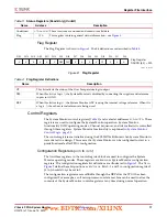
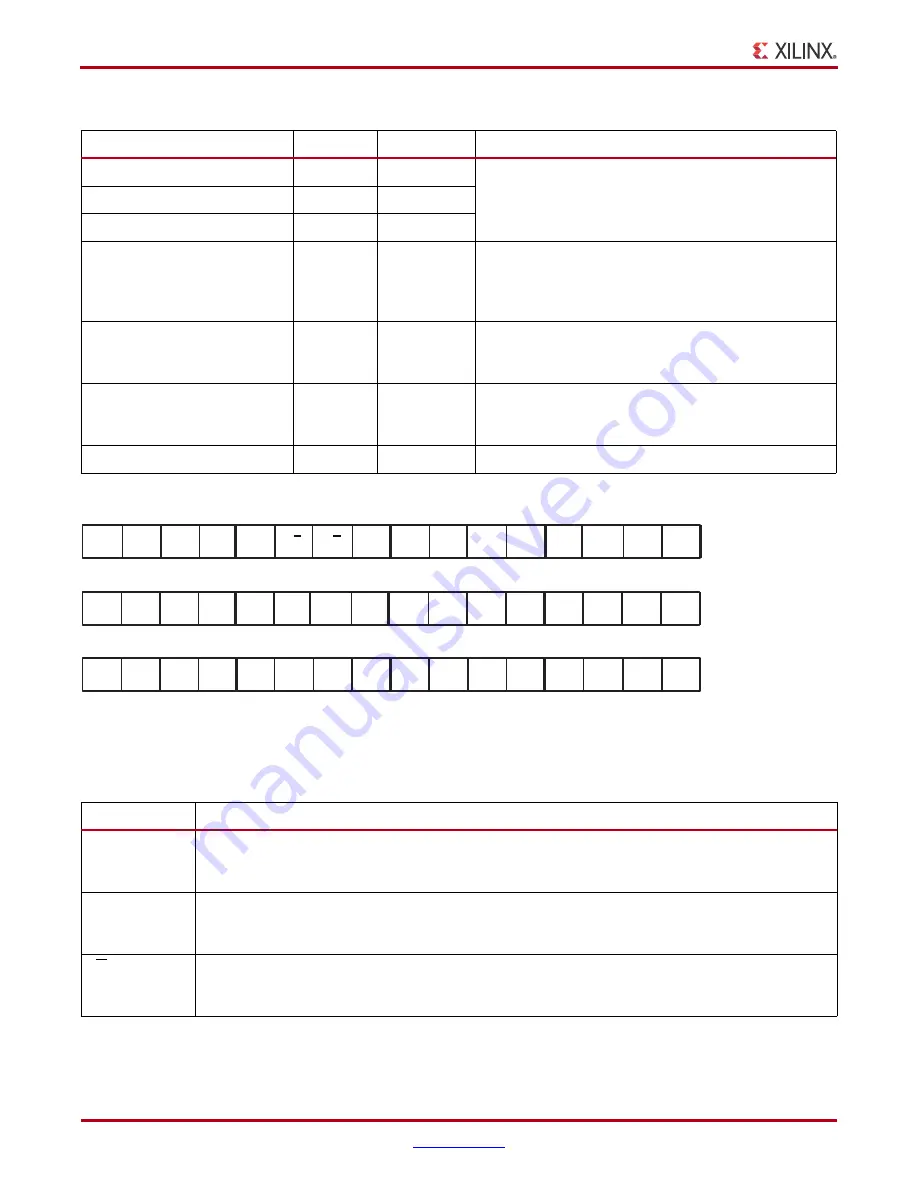
describes the bit-position functionality in configuration registers 0 to 2.
Table 5:
Control Registers (Read and Write)
Name
Address
SW Attribute
Description
Configuration register 0
40h
INIT_40
These are System Monitor configuration registers (see
).
Configuration register 1
41h
INIT_41
Configuration register 2
42h
INIT_42
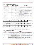
Test registers 0 to 4
43h
to
47h
INIT_43 to
INIT_47
These are System Monitor Test registers. The default
initialization is
0000h
. These registers are used for
factory test and should be left at the default
initialization.
Sequence registers
48h
to
4Fh
INIT_48 to
INIT_4F
These registers are used to program the Channel
Sequencer function in System Monitor (see
Alarm registers
50h
to
57h
INIT_50 to
INIT_57
These are the alarm threshold registers for the System
Monitor alarm function (see
).
Undefined
58h
to
7Fh
no attribute
Do not read or write these registers.
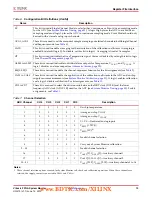
X-Ref Target - Figure 9
Figure 9:
Configuration Register Bit Definitions
Config Reg #1
DADDR [6:0] = 41h
Config Reg #2
DADDR [6:0] = 42h
Config Reg #0
DADDR [6:0] = 40h
DI0
DI1
DI2
DI3
DI4
DI5
DI6
DI7
DI8
DI9
DI10
DI11
DI12
DI13
DI14
DI15
CH4
CH3
CH2
CH1
CH0
ACQ
X
X
X
X
X
CAVG
AVG1 AVG0
BU
EC
UG370_09_060809
DI12
DI13
DI14
DI15
DI0
DI1
DI2
DI3
DI4
DI5
DI6
DI7
DI8
DI9
DI10
DI11
ALM0
ALM1
ALM2
OT
SEQ1 SEQ0
X
X
X
X
X
X
CAL0
CAL1
CAL2
CAL3
DI12
DI13
DI14
DI15
DI0
DI1
DI2
DI3
DI4
DI5
DI6
DI7
DI8
DI9
DI10
DI11
CD0
0
0
CD1
CD2
X
X
X
0
CD3
CD4
CD5
CD6
CD7
X
X
Table 6:
Configuration Bit Definitions
Name
Description
CH0 to CH4
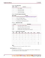
When operating in Single Channel mode, these bits are used to select the ADC input channel (refer
to
for more details). This channel could be an internal voltage or an
external (off
-chip) transducer.
shows the channel assignments.
ACQ
This bit is used in Single Channel mode to increase the acquisition time available for external analog
inputs in Continuous Sampling mode by 6 ADCCLK cycles (see
). The
acquisition time is increased by setting this bit to logic 1.
BU
This bit is used in Single Channel mode to select either Unipolar or Bipolar operating mode for
the ADC analog inputs (see
). A logic High places the ADC in differential
mode and logic 0 places the ADC in unipolar mode.
www.BDTIC.com/XILINX


