Virtex-6 FPGA System Monitor
9
UG370 (v1.1) June 14, 2010
System Monitor Primitive
Table 1:
System Monitor I/O
Port
I/O
Description
DI[15:0]
Inputs
Input data bus for the dynamic reconfiguration port.
(2)
DO[15:0]
Outputs
Output data bus for dynamic reconfiguration port.
(2)
DADDR[6:0]
Input
Address bus for the dynamic reconfiguration port.
(2)
DEN
(1)
Input
Enable signal for the dynamic reconfiguration port.
(2)
DWE
(1)
Input
Write enable for the dynamic reconfiguration port.
(2)
DCLK
Input
Clock input for the dynamic reconfiguration port.
(2)
DRDY
(1)
Output
Data ready signal for the dynamic reconfiguration port.
RESET
(1)
Input
Reset signal for the System Monitor control logic.
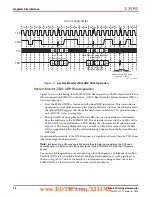
CONVST
(3)
Input
Convert start input. This input is used to control the sampling instant on the ADC input
and is only used in Event Mode Timing (see
Event-Driven Sampling, page 36
). This
input comes from the general-purpose interconnect in the FPGA logic.
CONVSTCLK
(3)
Input
Convert start input. This input is connected to a global clock input. Like CONVST, this
input is used to control the sampling instant on the ADC inputs and is only used in
Event Mode Timing. This input comes from the local clock distribution network in the
FPGA logic. Thus for the best control over the sampling instant (delay and jitter), a
global clock input can be used as the CONVST source.
V
P
, V
N
Input
One dedicated analog-input pair. System Monitor has one pair of dedicated analog
-
input pins that provide a differential analog input. When designing with the System
Monitor feature, but not using the dedicated external channel of V
P
and V
N
, the user
should connect both V
P
and V
N
to the analog ground.
V
AUXP
[15:0],
V
AUXN
[15:0]
Inputs
Sixteen auxiliary analog
-input pairs. In addition to the dedicated differential analog
input, System Monitor uses 16 differential digital
-input pairs as low-bandwidth
differential analog inputs. These inputs are configured as analog during FPGA
configuration. These inputs can also be enabled pre-configuration via the JTAG port.
See
and
Auxiliary Analog Inputs, page 40
.
ALM[0]
(1)
Output
System Monitor temperature
-sensor alarm output.
ALM[1]
(1)
Output
System Monitor V
CCINT
-sensor alarm output.
ALM[2]
(1)
Output
System Monitor V
CCAUX
-sensor alarm output.
OT
Output
Over-Temperature alarm output.
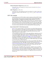
CHANNEL[4:0]
Outputs
Channel selection outputs. The ADC input MUX channel selection for the current ADC
conversion is placed on these outputs at the end of an ADC conversion.
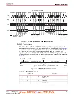
EOC
(1)
Output
End of Conversion signal. This signal transitions to an active High at the end of an ADC
conversion when the measurement is written to the status registers (see
).
EOS
(1)
Output
End of Sequence. This signal transitions to an active High when the measurement data
from the last channel in the auto sequence is written to the status registers (see
).
BUSY
(1)
Output
ADC busy signal. This signal transitions High during an ADC conversion. This signal
also transitions High for an extended period during an ADC or Supply Sensor
calibration.
www.BDTIC.com/XILINX


